1. Quick Ways to Learn Modbus
1.1 Register Mnemonics
As a beginner, one might find the concepts of the Modbus protocol awkward, repetitive, and hard to distinguish, such as Coil Status, Discrete Input Status, Holding Register, and Input Register.
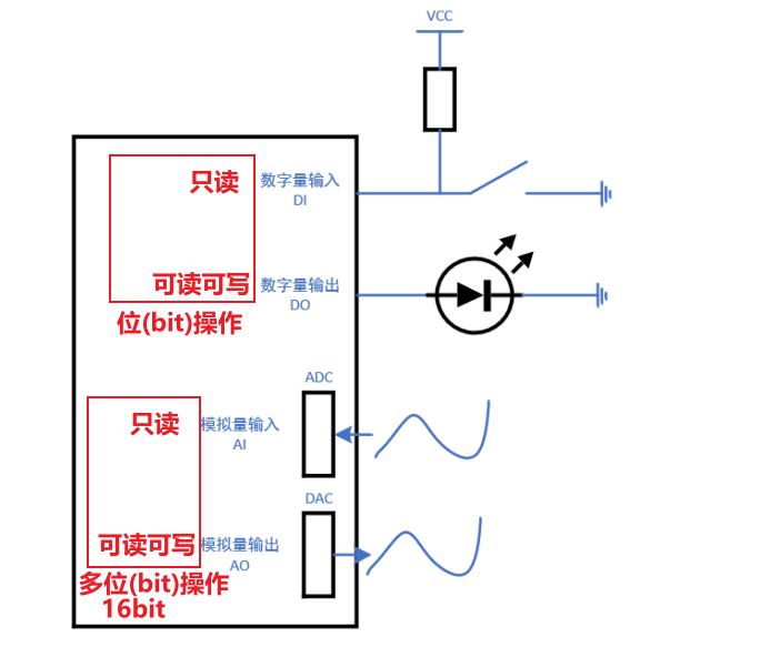
Returning to the essence of the matter, in the field of industrial control PLC, it involves the input and output of digital signals and the input and output of analog signals, as shown in the figure below:
For software development:
• To obtain the button input status, a single bit of data is read;
• To control an LED, a single bit of data needs to be output, and to read the current state of the LED, a single bit of data can also be read;
• To read an analog signal, multi-bit data is read, such as 16-bit data;
• To output an analog signal, multi-bit data is written, such as 16-bit data; the current value of the “analog output” can also be read.
In the figure above, the “Digital Input DI” is read-only, “Digital Output DO” is read-write, “Analog Input AI” is read-only, and “Analog Output AO” is read-write.
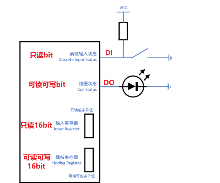
In the figure above, “Analog Input AI” and “Analog Output AO” both represent “multi-bit values”; these “multi-bit values” are not limited to representing “analog quantities” but can also represent “multi-bit digital quantities.” After expanding the meanings of AI and AO, it is shown in the figure below:
For software development:
• To obtain the button input status, a single bit of data is read;
• To control an LED, a single bit of data needs to be output, and to read the current state of the LED, a single bit of data can also be read;
• To read parameters, the “Input Register” is read, obtaining multi-bit data, such as 16-bit data;
• To set parameters, the “Holding Register” is written, writing multi-bit data, such as 16-bit data; the “Holding Register” can also be read.
In electronic systems, whether it is a single bit value or a multi-bit value, it is stored in registers. According to the figure above, these registers can be divided into four categories:
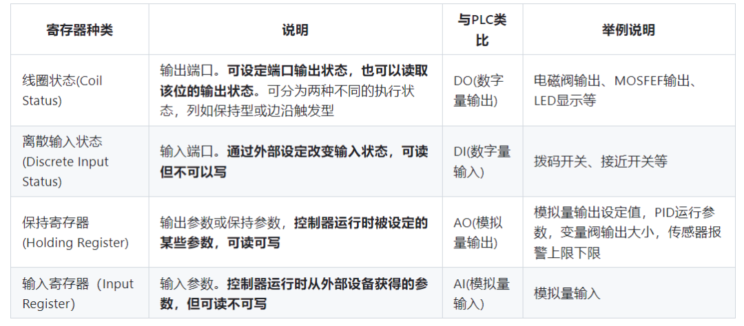
In Modbus, multi-bit operations are always 16 bits (2 bytes), summarized as follows:
• The registers involved in bit operations are of 2 types: Coil Status (read-write), Discrete Input Status (read-only);
• The registers for 16-bit operations are of 2 types: Holding Registers (read-write), Input Registers (read-only).
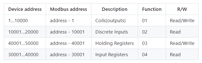
A device may have multiple “Coil Status”, multiple “Discrete Input Status”, multiple “Holding Registers”, and multiple “Input Registers”. How to distinguish a specific register among these types? They have “register addresses”, as shown in the figure below:
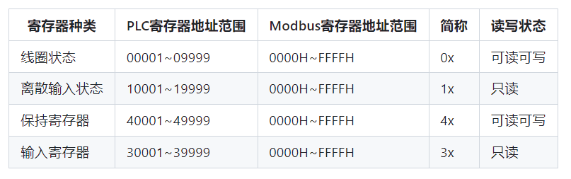
In the table above, the registers for “Coil Status” N and “Discrete Input Status” N are two different registers.
A simple mnemonic method:
• “Even-numbered registers” are read-write, such as “0x” and “4x”;
• “Odd-numbered registers” are read-only, such as “1x” and “3x”;
• “0x” and “1x” are bit registers;
• “3x” and “4x” are 16-bit registers.
1.2 Protocol Mnemonics
Modbus is a master-slave protocol, as shown in the figure below:
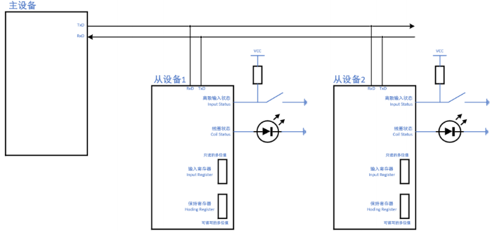
The data sent by the master control must contain the following information:
• Device Address: Whether you want to access Slave Device 1 or Slave Device 2 (the slave device recognizes that the device address matches its own address before processing the data packet from the master device);
• Which type of register to access, whether to read or write: this is called the Function Code (for example, reading the discrete input register);
• Starting Register Address, Number of Registers: this is defined in the data (related to the function code: for example, in the above case, it needs to specify which discrete input register to read, whether to read one or multiple);
• To ensure reliable data transmission, a CRC check code is also included.
Taking the Modbus RTU protocol as an example, the format of the data packet sent by the master control is as follows:

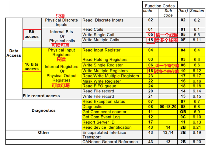
What are the function codes? Common function codes are as follows:
• Read Coil Status (01);
• Read Discrete Input Status (02);
• Write Single Coil (05), Write Multiple Coils (15);
• Read Holding Register (03);
• Read Input Register (04);
• Write Single Holding Register (06), Write Multiple Holding Registers (16).
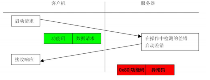
The format of the data is determined by the function code. Taking “Read Coil Status” as an example, the request sent by the master control and the response packet returned by the slave device, or the error packet returned by the slave device, are formatted as follows:
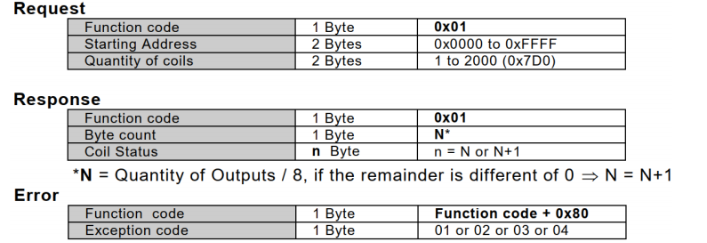
In the Function Code, 0x01 indicates reading coils. The Starting Address of the register is 16 bits, with the high byte transmitted first, followed by the low byte. The Quantity of Coils is also 16 bits, with the high byte transmitted first, followed by the low byte.
How many data does the response packet reply (N in the above figure)? N = Quantity of Coils / 8; if the remainder is not equal to 0, then N is increased by 1. For example, if Quantity of Coils = 9, then 2 bytes will be returned.
In the “Modbus_Application_Protocol_V1_1b3.pdf”, the following function table is listed. Based on this table and the examples in “5.5 Detailed Explanation of Modbus Function Codes”, one can have a good understanding of the Modbus RTU protocol.
2. Introduction to Modbus
2.1 Background
Modbus was born in 1979 at Modicon, which was later acquired by Schneider Electric. Modbus provides a common language for devices to communicate with each other and is the world’s first true bus protocol used in industrial sites. Modbus has become the industry standard for communication protocols in the industrial field and is now a commonly used connection method between industrial electronic devices. As the most widely used protocol in the industrial field, Schneider has transferred the ownership of the Modbus protocol to the IDA (Interface for Distributed Automation) organization to better promote and popularize the distributed application of Modbus based on Ethernet (TCP/IP), and established the Modbus-IDA organization, which further promotes the widespread application of the Modbus protocol.

2.2 What is Modbus?
2.2.1 Overview of Modbus
The Modbus protocol is a widely used general communication protocol in today’s industrial control field. Through this protocol, controllers can communicate with each other or with other devices over a network (such as Ethernet). The Modbus protocol uses master-slave communication technology, where the master device actively queries and operates the slave device. The protocol used by the master control device is called Modbus Master, and the protocol used by the slave device is called Modbus Slave.
Typical master devices include industrial PCs and industrial controllers; typical slave devices include PLC programmable controllers, etc. With it, control devices produced by different manufacturers can be connected into an industrial network for centralized monitoring.
The Modbus protocol defines a message structure that a controller can recognize and use, regardless of the network used for communication; it also describes the process for the controller to request access to other devices, how to respond to requests from other devices, and how to detect and record errors, and establishes a unified structure and content for the message domain. When communicating on a Modbus network, the Modbus protocol determines that each controller must know its device address, recognize messages sent by address, and decide what action to take. If a response is needed, the controller will generate feedback information and send it via the Modbus protocol.
The Modbus communication physical interface can use serial ports (including RS232, RS485, RS422, etc.) or Ethernet ports. Its communication follows the following process:
• The master device sends a request to the slave device;
• The slave device analyzes and processes the master’s request, then sends the result back to the master device;
• If any error occurs, the slave device will return an exception function code.
This protocol defines a message structure that a controller can recognize and use, regardless of the network used for communication. It describes the process for a controller to request access to other devices, how to respond to requests from other devices, and how to detect and record errors. It establishes a common format for the message domain structure and content.
When communicating on a Modbus network, this protocol determines that each controller must know its device address, recognize messages sent by address, and decide what action to take. If a response is needed, the controller will generate feedback information and send it via the Modbus protocol. On other networks, messages containing the Modbus protocol are converted into frames or packet structures used on that network. This conversion also extends the methods for addressing, routing paths, and error detection based on specific networks.
Modbus operates on a request/response basis, where the master station sends instructions, which can be broadcast or unicast to a specific slave station; the slave responds to the instructions and answers as required or reports exceptions. When the master does not send a request, the slave will not send data on its own, and there can be no direct communication between slaves.
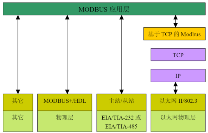
MODBUS is an application layer messaging protocol located at layer 7 of the OSI model. It provides client/server communication between devices connected on different types of buses or networks.
The Modbus communication stack is as follows:
2.2.2 Features of Modbus
The Modbus communication protocol has the following characteristics:
• The Modbus protocol standard is open, publicly published, and has no royalty requirements. Users can obtain and use the Modbus protocol for free, without paying license fees or infringing on intellectual property rights.
• The Modbus protocol supports multiple electrical interfaces, such as RS232, RS485, TCP/IP, etc., and can also be transmitted over various media, such as twisted pair, fiber optic, infrared, and wireless.
• The Modbus protocol message frame format is simple, compact, and easy to understand. It is easy for users to understand and use, and for manufacturers to develop and integrate, facilitating the formation of industrial control networks.
• Reliability: Modbus is the oldest industrial automation communication protocol. It is simple to use and program, resulting in a low learning curve.
• Legacy Infrastructure: Many manufacturers have invested heavily in early automation. Modbus is very friendly to configuring, DLR, nodes, substations, and other infrastructures that may be phased out by newer or more advanced protocols.
• Quick Deployment: Modbus can be easily and immediately integrated into SCADA and other control systems.
• Flexibility: Modbus has adapted to emerging technologies. For example, Modbus TCP can be converted through gateways to integrate with LAN and remote control systems. It can also utilize network and cloud-based platforms.
• Simplicity: Due to its simple communication, it can be easily extended to new technologies. For example, Modbus TCP/P can be deployed quickly due to its simple instruction set. It can also work with Ethernet without the need for additional chips or boards.
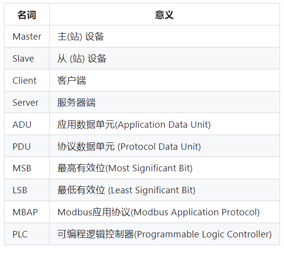
2.2.3 Common Modbus Terminology
2.2.4 Modbus Transaction Processing
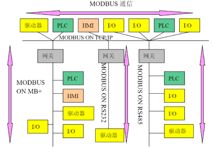
The Modbus protocol allows simple communication within various network architectures, enabling each device (including PLCs, HMIs, control panels, drivers, motion controls, and input/output devices) to initiate remote operations using the Modbus protocol. Mutual communication can occur over Modbus based on serial links and Ethernet (TCP/IP). Some gateways allow communication between several buses or networks using the MODBUS protocol.
Examples of MODBUS network architectures:
Modbus is a request-response protocol and provides a unified function code for data transmission services. The Modbus function code is one of the elements of the Modbus request/response PDU (Protocol Data Unit). The so-called PDU is a simple protocol data unit defined by the Modbus protocol that is independent of the underlying communication layer. The mapping of the Modbus protocol on a specific bus or network can introduce some additional fields on the ADU (Application Data Unit) to enable complete and accurate data transmission.
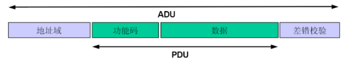
To seek a concise communication format, the Modbus protocol defines the PDU model, which is the format of function code + data, and to adapt to various transmission modes, necessary prefixes (such as address fields) and suffixes (such as error checks) are added to the PDU to form the ADU model (see the figure below).
The general MODBUS frame is as follows:
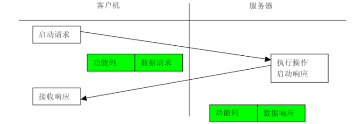
The Modbus transaction processing process:
The host device (or client) creates a Modbus application data unit to form a query message, where the function code indicates the operation to be performed on the slave device (or server). The function code occupies 1 byte, and the valid code range is decimal 1 to 255 (where 128 to 255 is reserved for exception responses). After creating the query message, the host device (or client) sends the message to the slave device (or server), and after receiving the message, the slave device (or server) takes the corresponding action according to the function code and returns the response message to the host device (or client), as shown in the figure below:
Modbus Transaction Processing (No Exception)
If no errors related to the requested Modbus function appear in a correctly received Modbus ADU, the slave device (or server) will return a normal response message. If errors related to the requested Modbus function occur, the function code field of the response message will include an exception code, and the host device (or client) can determine the next operation based on the exception code; for exception responses, the server returns a code equal to the original function code, setting the most significant bit of that original function code to logical 1 to notify the master device (client). As shown in the figure below:
Modbus Transaction Processing (Exception Response)
3. Modbus Software and Usage
3.1 Overview of Modbus Software
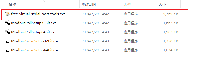
To better learn and understand Modbus, three software tools are introduced: Modbus Poll (master device), Modbus Slave (slave device), and virtual serial port software. With these three tools, we can conduct some basic experiments on a PC and intuitively observe communication data, deepening our understanding. We call this the essential trio for learning Modbus, which is a great way to get started.
3.2 Modbus Poll (Master Device)
3.2.1 Overview of Modbus Poll
Modbus Poll is a Modbus master device simulator used to test and debug Modbus slave devices, facilitating observation of various message data during the Modbus communication process. This software supports Modbus RTU, ASCII, and TCP/IP. It helps developers test Modbus slave devices or other Modbus protocol testing and simulation. It supports multi-document interface, meaning multiple slave devices/data domains can be monitored simultaneously. Each window simply sets the slave device ID, function, address, size, and polling interval. You can read and write registers and coils from any window. If you want to change a single register, simply double-click the value. Alternatively, you can change multiple register/coils values. It provides various data formats, such as float, double precision, and long integers (byte order can be swapped). This software supports Modbus RTU, ASCII, TCP/IP, and other protocol modes.
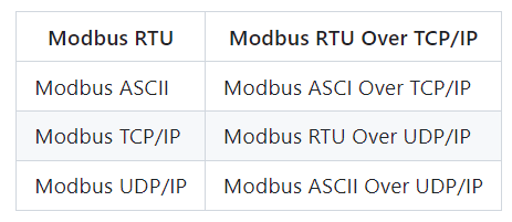
Modbus Poll supports the following protocol modes:
3.2.2 Using Modbus Poll
Click the link to obtain the software and install it as prompted; link:
https://pan.baidu.com/s/1SpTRz6Z1XlkoCZjDozwqog Extraction code: timc
After downloading, the interface is as follows:
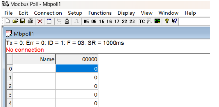
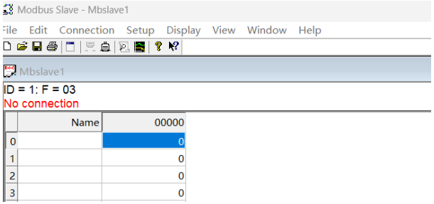
Status bar:
• Tx = 0 indicates the number of data frames sent to the master station, which is 0 times in the figure;
• Err = 0 indicates the number of communication errors, which is 0 times in the figure;
• ID = 1 indicates the device address of the simulated Modbus slave device, which is 1 in the figure;
• F = 03 indicates the Modbus function code used, which is function code 03 in the figure;
• SR = 1000ms indicates the sending cycle, once every 1S.
The red text part indicates the current error status, “No Connection” indicates a disconnected state.
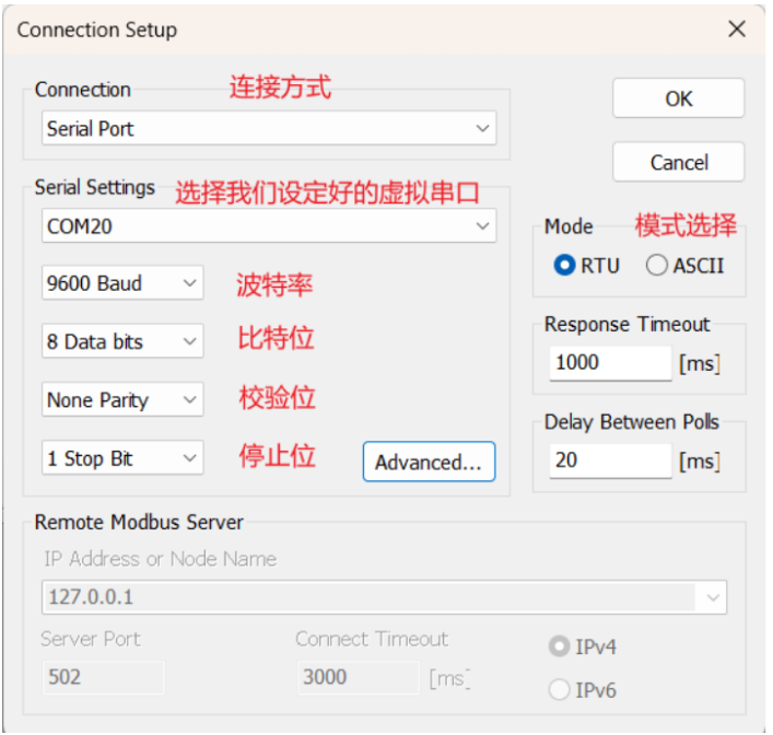
Establishing a connection:
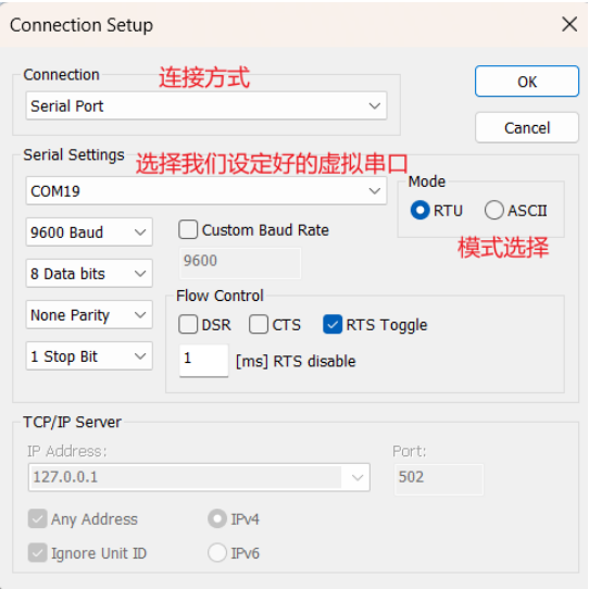
Click Connection->Connect to enter the configuration page, select the connection you want, choose the virtual serial port you created, and select the mode, for example: we choose the serial port connection method, select the RTU mode corresponding to our Modbus RTU protocol; next, set the baud rate, bit count, parity bit, and stop bit, as shown in the figure below:
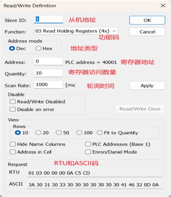
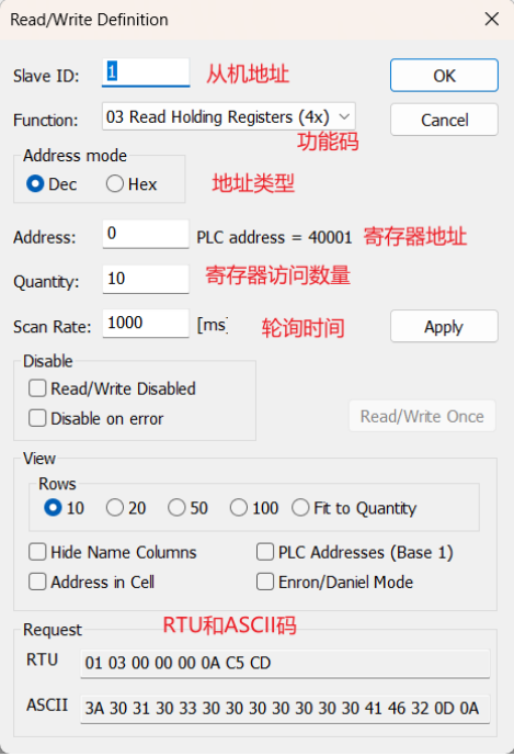
Setting parameters: Click Setup->Read/Write Definition to enter the configuration page, configure the slave address, function code, address type, register address, access quantity, polling time, as shown in the figure below:
3.3 Modbus Slave (Slave Device)
3.3.1 Overview of Modbus Slave
Modbus Slave is a slave device simulator that can simulate up to 32 slave devices/address domains. Each interface provides OLE automation support for EXCEL reports. It is mainly used to simulate Modbus slave devices, receive command packets from the master station, and return data packets. It helps developers of Modbus communication devices simulate and test the Modbus communication protocol, making it easier to observe various message data during Modbus communication; it can simulate up to 32 Modbus slave devices in 32 windows. It has a user interface similar to Modbus Poll and supports functions 01, 02, 03, 04, 05, 06, 15, 16, 22, and 23, monitoring serial port data.
Modbus Slave supports the following protocol modes:

3.3.2 Using Modbus Slave
Obtain the software link as above, after downloading, the main page is shown as follows:
Establishing a connection:
Click Connection->Connect to enter the configuration page, select the connection you want, choose the virtual serial port you created, and select the mode, then set the baud rate, bit count, parity bit, and stop bit, as shown in the figure below:
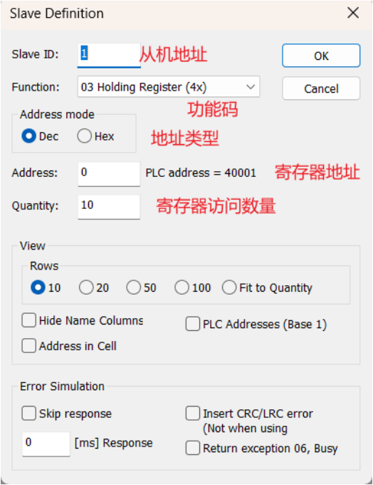
Setting parameters: Click Setup->Read/Write Definition to enter the configuration page, configure the slave address, function code, address type, register address, access quantity, as shown in the figure below:
There are two points we need to pay attention to:
One is: The Function list box selects the functions of 0x~4x, which represent storage areas 0, 1, 3, and 4.
Output coils
Input coils
Holding registers
Input registers
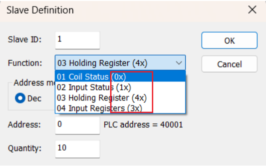
The Modbus protocol specifies four storage areas: 0, 1, 3, and 4, where storage areas 0 and 4 are read-write, while 1 and 3 are read-only.

Secondly: The Address item needs to be emphasized; the Address indicates the Modbus register address, and its value range has a mapping relationship with the device register address, as shown in the table below:
Here we will only briefly introduce the address and storage areas, and we will elaborate on them in detail later.
3.4 Virtual Serial Port Software
3.4.1 Overview of the Software
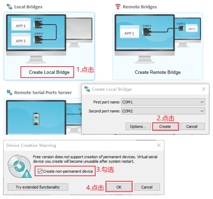
The virtual serial port tool can create two interconnected serial ports, as shown in the figure below:

For example, the Modbus Poll tool sends data from COM1 to COM2, and Modbus Slave reads the data from COM2. By using the virtual serial port, you can experience Modbus Poll and Modbus Slave without using a development board.
Open the software in the red box below:
3.4.2 Using the Virtual Serial Port

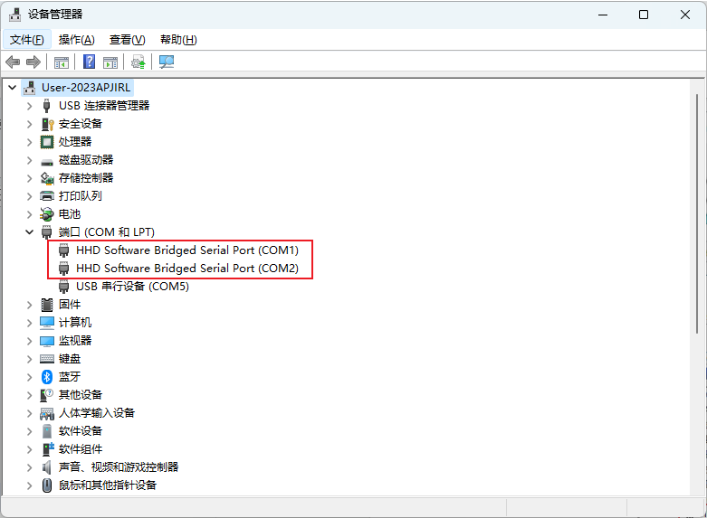
Open Device Manager, and you can see the following serial ports:
3.5 Interconnection of Modbus Poll and Modbus Slave
Next, we will conduct an interconnection experiment between Modbus Poll and Modbus Slave, visually demonstrating the Modbus data flow. Based on the previous settings, we already know how to use the essential trio for learning Modbus. Now we will experiment with this trio. First, open the VSPD virtual serial port software and set up the virtual serial port. Here we will use the settings of COM1 and COM2 as an example, and then we will configure our Modbus Poll and Modbus Slave.
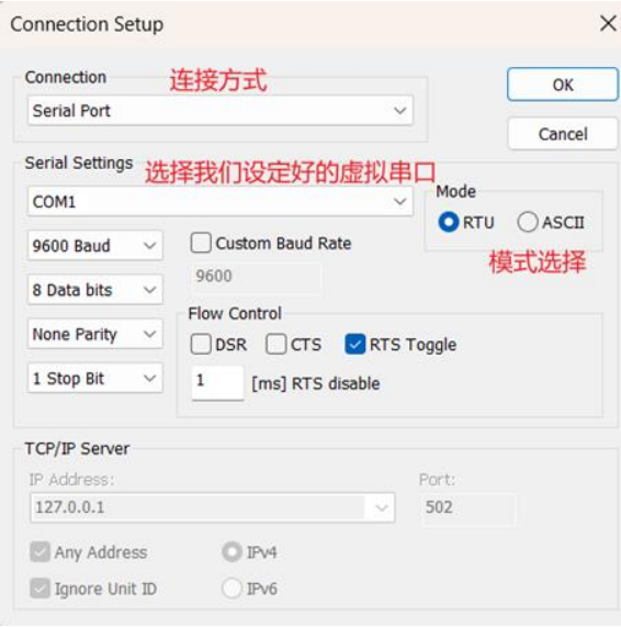
We first open the Modbus Slave side, set the connection, select Serial Port connection, choose the COM1 we set, and select RTU mode, as shown in the figure below:
Modbus Slave Connection Settings
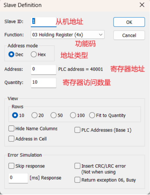
In setting parameters, we set the slave address to 1 (you can set it arbitrarily), the Function item is set to 03 Holding Register (4x), the address type is set to DEC (decimal format), the starting address is set to 0, and the number of registers to access is set to 10, as shown in the figure below:
Modbus Slave Parameter Settings
Next, we will set the Modbus Poll side, and the setting method corresponds one by one with the Modbus Slave side, as shown in the figure below:
Modbus Poll Connection Settings
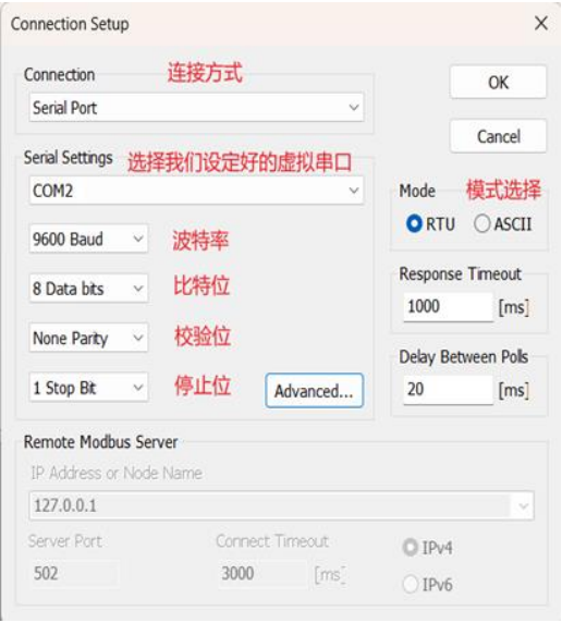
Note that the serial port must be selected as COM20, and other serial port parameters must correspond one by one.
Modbus Poll Parameter Settings
After the setup, we connected our master device and slave device to the COM1 and COM2 we set, allowing us to observe the current register’s reading status.
We double-click the value of 0 in the Modbus Poll (master device side), which opens the value setting window as shown in the figure below:
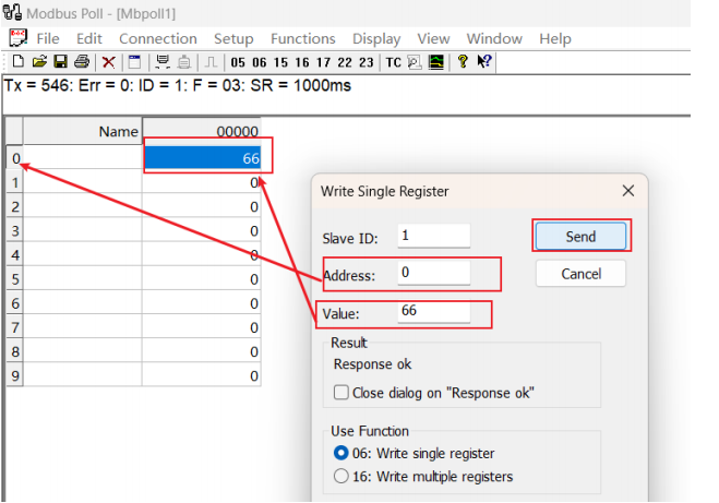
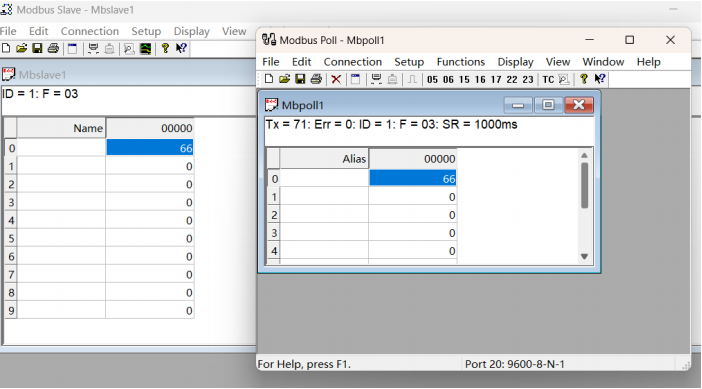
Change the value to 66, click Send, and open Modbus Slave (slave device side) to find that it has also changed, as shown in the figure below:
We can also open Modbus Poll, click Display, select Communication, and check the sent message:
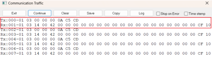
TX is the message sent by our master station, and RX is the message returned by the slave station.