
Click the blue text above to follow for more first-hand resources on electronic competitions.
Little Creation
Little Creation
Little Creation
In preparation for the electronic competition, Little Creation has launched a learning section. Starting today, we will update the technical department’s learning notes in real-time for everyone’s reference.
Microcontroller Learning Notes
Learning Objectives
Objective 1: Color Light Control
Example: Color Light Control
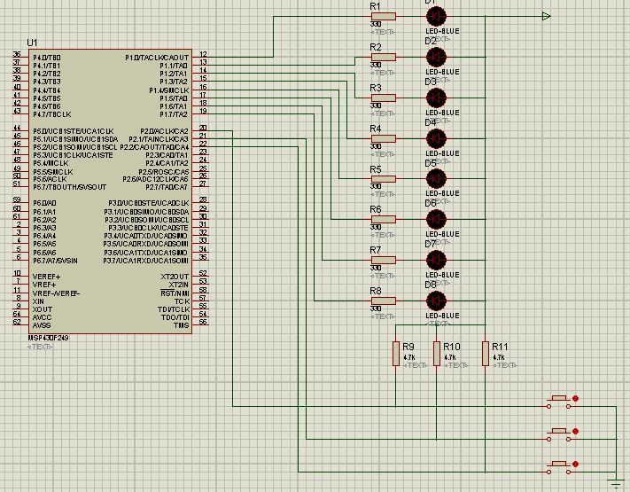
Task Requirements: Use the MSP430 microcontroller’s P1 port to control 8 light-emitting diodes D1~D8. The P1 port is connected to three switches K1~K3. When K1 is closed, D1 and D4 blink for 1 second; when K2 is closed, D2 and D5 blink for 2 seconds; when K3 is closed, D1~D8 blink in a loop for 1 second.
Analysis: An LED is a semiconductor device that emits light when the voltage across it exceeds 1V, with a conduction current of about 5mA. The greater the conduction current, the higher the brightness, but if the current is too high, it will burn out the diode, generally controlled between 3~20mA. Here, a resistor is connected in series with the LED to limit the current through the LED, hence this resistor is called a “current-limiting resistor,” typically chosen between 300Ω~1000Ω. The I/O port of the MSP430F249 microcontroller can output a maximum current of 6mA, with a total current not exceeding 48mA. When the I/O port outputs “0,” it can absorb a maximum current of 40mA. Therefore, the design uses the microcontroller’s I/O port to control the negative side of the LED.
Objective 2: Simulate Control of WS2812B and Its Array Using Microcontroller
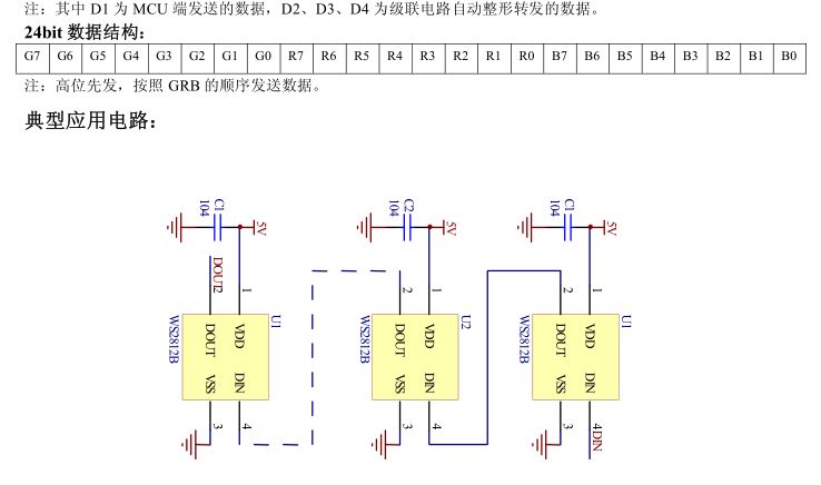
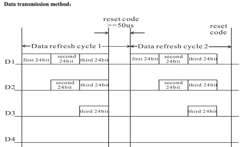
Although the microcontroller outputs 8-bit parallel data, the array uses a 24-bit serial digital signal for control, so we need to convert char-type data to use a single pin for serial signal input.
Summer
Sunshine
Objective 3: Use Java to Parse GIF Files and Compress, Convert to Character Array
Objective 4: Implement Network Communication Technology for Microcontroller Using ESP8266
Objective 5: Write Server-Side Software Using Java Web to Send Information to Microcontroller Over the Network
Technical Learning Log
1.Batch Modify Component Parameters in Proteus
Using the PAT tool, first select all resistors that need to be modified, then use the wrench icon in the toolbar, set String to value=330, select Assign in Action, and choose Global Tagged in Apply to.
In the image, under Standard Properties, REF refers to the component name, VALUE refers to the component value, and DEVICE refers to the component type, so component posture cannot be modified in bulk. You can add components with the same posture parameters by copying and pasting.
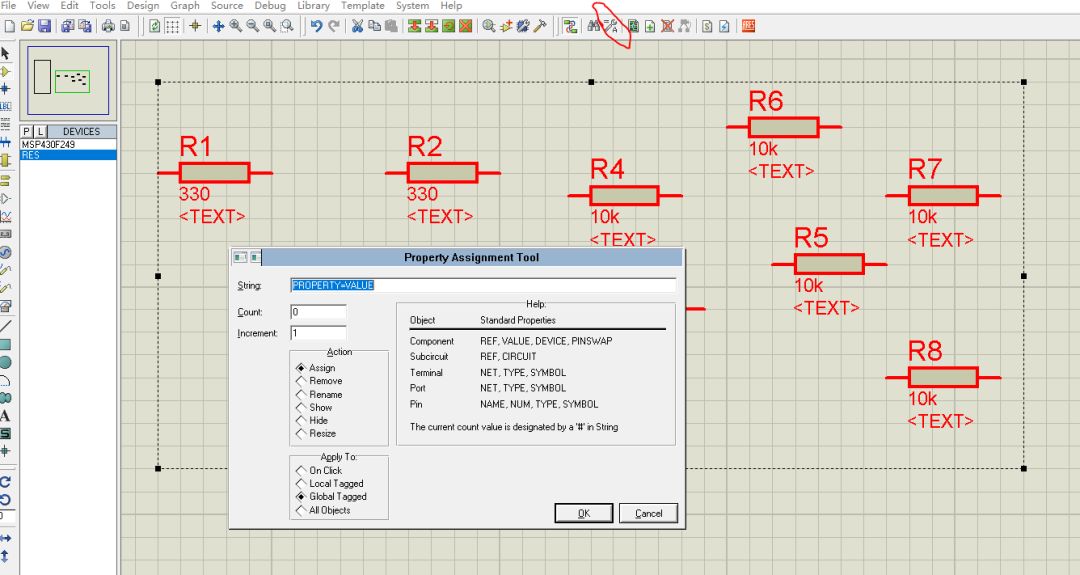
Quick Numbering for Batch Modifying Component Names
String: REF=D# Action: Rename
After the operation, you should also press ctrl+z.

2. Adding Components in Proteus
Resistor: Click the component button, search for “res,” all sub-categories.
LED: optoelectronics, LED – four colors.
Switch: switches and relays.
Ground: left toolbar (model selection toolbar) terminals mode -> ground.
Power is under the same category as power.
3. Understanding Microcontroller Development Software
-
Division of Labor Between Proteus and IAR, CCS in Microcontroller Design: IAR or CCS is responsible for compiling C language, generating .hex, .txt, or .d90 files, which are imported into Proteus.
Bug1Proteus may fail to import .d90 files, resulting in the source code not being found, and the microcontroller behaves as if all outputs are high, failing to perform the corresponding functions. Based on the debugging results of bug3, it is inferred that this may be due to the program itself. The issue of not finding the source code needs further analysis.
-
Comparison of Proteus and Multisim: The former is used for digital and microcontroller simulation, while the latter is used for analog simulation.
-
Consideration: Can other non-microcontroller-specific C language development environments be used for MSP430 programming, such as Eclipse CDT or even Visual Studio? What unique features do professional MSP430 microcontroller development environments have?
Click the blank area below to view hidden content ▼
Answer: No, the programming language for MSP430 has differences from standard C language, for example, the use of #pragma VECTOR+ functions may not compile with general C language compilers, thus professional microcontroller development environments have specialized C language compilers and function libraries.
4. Introduction to Code Composer Studio (CCS)
The interface and file management approach are completely consistent with Eclipse Jee, and the shortcut keys are basically the same. Ctrl+shift++ enlarges the font size, but it cannot check errors in real-time like Jee.
Bug2 CCS installation issues:
CCS Debug Assertion Failed
After installing CCS7.1, compiling the project results in an error as shown below:
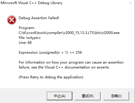
I initially thought this situation was caused by an unsuccessful installation of CCS, but the same issue occurred when trying to install other versions.
So I logged into TI’s wiki to find the cause, which states in the installation section:
Ensure that your Username does not have any non-ascii characters, and that you are installing CCS to a directory that does not have any non-ascii characters.
A temporary directory using the Username is created during installation, and Eclipse is unable to handle non-ascii characters. If your Username does have non-ascii characters, please create a temporary admin user for installing CCS.
Since Eclipse needs to compile in a pure ASCII environment, our username must also use only ASCII characters.
It turned out that my username contained Chinese characters, so how do I change my username?
My system uses a Microsoft account to log in, but the user folder name is “apple.” Changing to a local account “apple” did not resolve the issue. I checked the installation directory, which is E:\Program Files (x86)\ti\, and it does not contain Chinese characters, so I switched the workspace to English, which resolved the issue.
5. Learning about msp430f249.h
The file path issue for C language includes: <> only checks standard paths, while “” first checks the current path and then the standard path.
How to implement multi-file programming in C language:
Option 1: Write the function implementation in a header file and include it at the beginning;
Option 2: main.c file: place the main function; myfile.h: declarations of 3 functions; myfile.c: implementations of 3 functions.
In fact, the #include mechanism is quite simple; it directly copies the contents of the included file to the location of the #include statement and replaces the #include statement. The difference between .h and .c files in C language is that the compiler treats these two types of file extensions differently. .c files are compiled into .o / .obj files, while .h files do not directly participate in compilation. This facilitates the management and use of C programs; .h is a header file, generally storing function declarations, arrays, and defined variables, while .c is a source file that implements the function of the program.
Observe msp430.h, which includes various models of MSP header files.
Below are three custom types for microcontroller state parameters:

For example, for port one, we have:
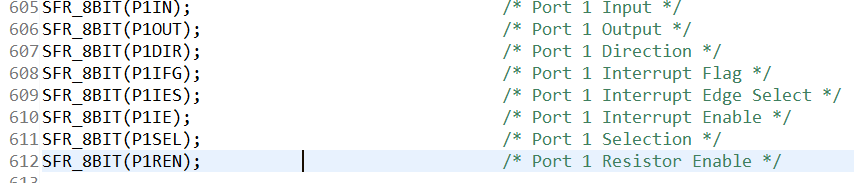
6. Configuring CCS Export Methods
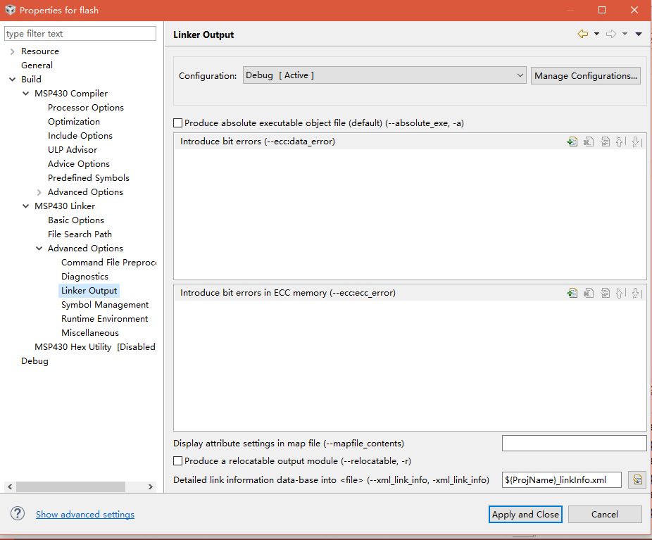
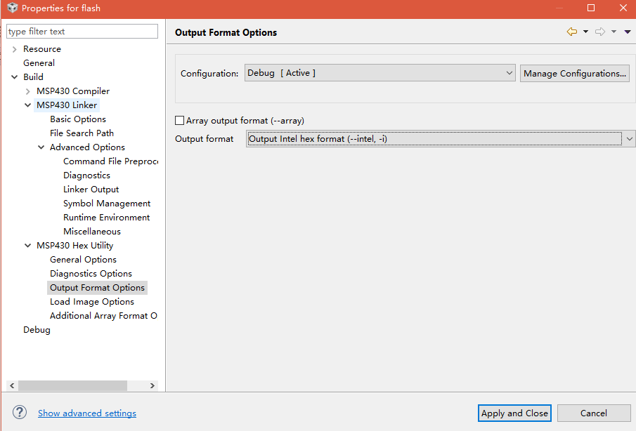
CCS exports to .out and .map files, and the configuration should be set to Debug mode. The .out file is the output file, and the .map file contains link information; their names can be adjusted, but this file cannot be used by Proteus.
Therefore, you should enable the MSP430Hex Utility and change the output format to Intel hex format, but this format cannot be used in Proteus to view source code and debug.
Bug3 Analysis of the reasons for the failure of flash project simulation, checking software installation issues, output file format issues, circuit connection issues, and program issues.
I created a simpler introductory case to verify the software and output files: as shown in the image, the simulation was successful, and the content in the red circle seems to be redundant. The triangular component represents a 5-volt power supply. Note that in the MSP430’s output ports, p1.x (a total of 8) jointly output an 8-bit char.
Sunshine
7. Hexadecimal Representation of Microcontroller
When a char type (8-bit binary) data is represented in hexadecimal, only two digits are needed. When indicating the direction of input and output, P1DIR is often set to the maximum 0xFF.
8. MSP430 Outputs Active Low
Thus, it can be seen that the direction of the diode should be to the left. In p1.x, the larger the x, the higher the priority, indicating a higher bit number.
9. Compiling and Exporting C Language Files with CCS, Then Simulating with Proteus, but the .hex output file cannot be viewed in Proteus for source code and debugging. Does CCS have a compatible debug output format with Proteus?
No, CCS is generally not used in conjunction with Proteus. For the 51 microcontroller, Keil + Proteus can be used for joint debugging, while for the MSP430 microcontroller, IAR + Proteus is used together, and CCS is usually directly connected to hardware for debugging. First, connect the microcontroller to the computer, then click run -> load button to directly import the compiled file into the microcontroller, or click debug for hardware debugging.
Additionally, Proteus does not have the WS2812B component mentioned in Objective 2, and no related plugins can be found on the manufacturer’s WorldSemi website, so computer simulation is not possible, and only hardware debugging can be performed.
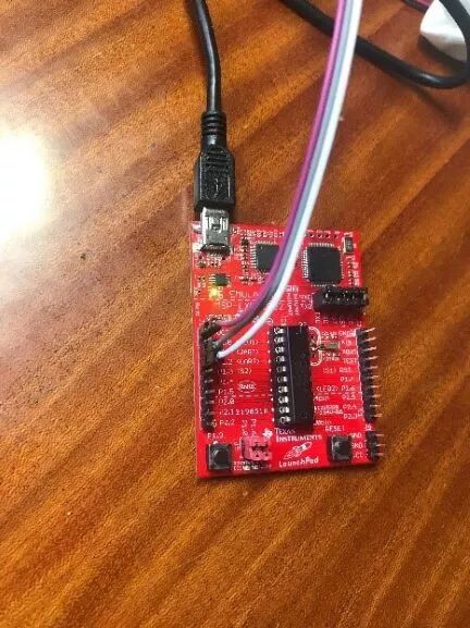
10. Testing the Hardware Debugging Function of MSP430G2553
The test code sets p1.x to low, but after importing, there are no diodes for verification, and hardware testing is temporarily impossible. The Proteus simulation also does not have the G2553 model.
How does the microcontroller connect to power and operate without a computer?
11. Software Modular Design
Module 1: Single Frame Display
Function: Input a single frame display scheme, convert it to a serial digital signal, and control the light strip.
Tools and Methods: Convert char-type data to 8-bit serial data, concatenate serial data, delay methods.
Interface: Number of lights, of unsigned int type; display scheme, which is a one-dimensional char array, with a length equal to the number of lights.
Module 2: Frame Generation (Animation Scheme)
Function: Generate the display scheme for each frame of the microcontroller and repeatedly execute Module 1 to form an animation.
Generation Scheme 1, Parse Video: Parse the pixels on a single frame of the video into a 2D character array, then arrange them into a one-dimensional character array according to the display screen row.
Generation Scheme 2: Transform based on an image (similar to Adobe Flash), generating a 2D character array from a one-dimensional character array.
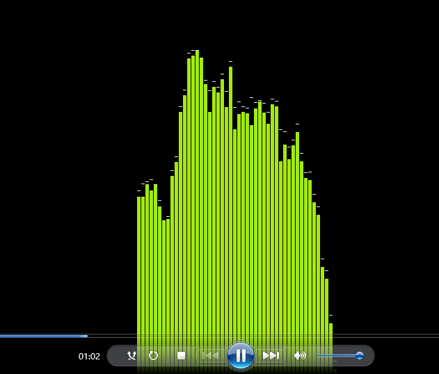
Generation Scheme 3: As shown, similar to the visualization effect of Windows Media Player, our microcontroller can process sound waveforms, first generating a 2D string array from the waveform, setting colors, and then concatenating each row into a one-dimensional array.
Interface: Scheme number, video, image, and transformation methods, wave function.
Module 3: Network Communication, Sensor Communication
Function: Control the display of the microcontroller, providing parameters for Module 2.
The network server sends video, images, and transformation methods, scheme numbers, and sound wave function signals from the sensors to the microcontroller.
12. Regarding Objective 2, the microcontroller’s computational load, storage capacity, and model selection
13. Review of C Language Related Knowledge Points
1) Data Structure of Arrays
Creating arrays in C language is different from Java; the size of Java arrays is determined at runtime, while the size of ordinary C arrays is determined at compile time because their addresses are not stored in heap memory but are stored together with the array elements. If you want to determine the size of an array at runtime, memory needs to be allocated manually. For example, the following array creation syntax is incorrect: int result[sizeof(c)]; where c is a function parameter, and it should be written as: int* result = malloc(sizeof(c));
2) Compilation Preprocessing Commands
#pragma preprocessing directives are used to provide additional information to the compiler. The #pragma directive is used by the compiler to provide machine or operating system functionality. Syntax: #pragma token
Different compilers in C may provide different uses of #pragma directives.
I found that in microcontroller C programming, a large number of macro definitions are used to implement a kind of “pseudo-object” similar to objects; a large number of bit operations are used to allow a single binary number to store multiple data, thus mimicking the feel of “object-oriented programming,” but the specific imitation methods need further observation.
14. Delay Issues in Microcontrollers
Delays in microcontrollers include hardware delays and software delays, which can be in microsecond and millisecond levels.
Software Delay: C language delay functions and timing functions, C++ generally uses clock(); or time(NULL); under windows.h for timing, returning types are clock_t and time_t, which need to be cast; the system library in microcontrollers does not include windows.h, so delays can only be achieved by wasting CPU cycles; when the delay is short and does not occupy too much CPU time, this method is suitable for software delays. Programs written in assembly language can easily control time, as we know the execution time of each statement, the execution time of each macro, and the time consumed by each segment of subroutine calls. Therefore, to create a more precise delay program in C language, one must study the assembly code generated by that segment of C program. The delay time equals the product of instruction execution time and the number of instruction loops.
What is the _nop_() function?
Hardware Delay: Method 1: Using the Watchdog Timer Mode
The basic parameters of the watchdog are WDTCTL, and the corresponding bit names are shown below:
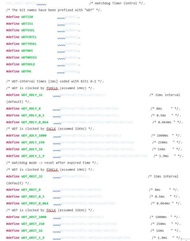
From the above settings, to set the watchdog mode with a timing of 250 milliseconds, at the beginning of the main program, set WDTCTL=WDT_ARST_250;
To set the timer mode, set the WDTTMSEL bit in the WDTCTL register.
Exercise: Use the watchdog timer to generate specific time interval interrupts, switching the LED light on for 1 second and off for 1 second.
The clock source for the watchdog timer can be either SMCLK or ACLK, with four division values, allowing only a few simple timing interval interrupts. The following program uses ACLK as the clock source.
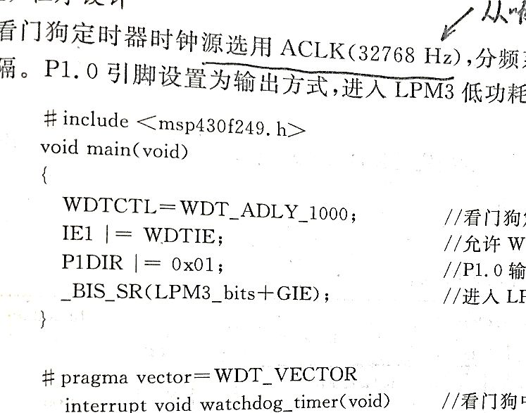
Questions:
What is the _BIS_SR function?
Why does the above program not require a while(1) loop?
Before using the watchdog timer mode, why was the WDTTMSEL not set?
How can it be seen that this program uses ACLK as the clock source?
In this program, what does the |= operator signify?
Note Author: Ge Hancheng

Looking forward to more exciting content?
Quickly scan the code to follow Little Creation~