Introduction
Industrial Control Systems (ICS) refer to the collection of personnel, hardware, policies, and software that affect the safety (Safety), information security (Security), and reliable operation of industrial production processes, including Distributed Control Systems (DCS), Supervisory Control and Data Acquisition (SCADA) systems, Programmable Logic Controllers (PLC), Remote Terminal Units (RTU), and relevant information systems such as Human-Machine Interfaces (HMI). With the development of information technology and industrialization, industrial control systems are widely used in key industries related to national defense, rail transit, power grids, petrochemicals, and water conservancy, which are crucial for the national economy and people’s livelihood. Due to their complexity and diversity, industrial control systems also face threats from various aspects. In recent years, with the development of new technologies in industrial control, some provisions of the original standards can no longer meet the safety design technical requirements under high reliability and real-time conditions, thus necessitating the addition of new content based on the characteristics of industrial control systems. This revision standardizes the security design technical requirements for network security level protection and the extended design requirements for industrial control systems, including the design technical requirements for the secure computing environment, security area boundaries, secure communication networks, and security management centers for Level 1 to Level 4 industrial control systems. It is applicable for guiding the design and implementation of safety technical solutions for industrial control systems under network security level protection and can also serve as a basis for information security intelligent departments to supervise, inspect, and guide industrial control systems.
1. Classification Objects
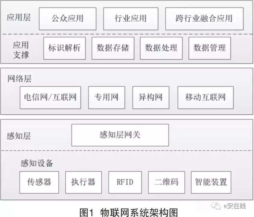
Industrial control systems and other information systems are divided into five layers from bottom to top according to functional hierarchy:
a) Level 0, Field Device Layer;
b) Level 1, Field Control Layer;
c) Level 2, Process Monitoring Layer;
d) Level 3, Production Management Layer;
e) Level 4, Enterprise Resource Layer, which includes other information systems (this standard does not make level protection design requirements for Level 4).
Based on the unique determinacy of the security units of industrial control systems, business objects, business characteristics, and business scope, the classification objects of industrial control systems are comprehensively determined. When determining the security level of the classification objects, factors such as asset value, production objects, and consequences should be comprehensively considered. The specific classification of industrial control systems should refer to relevant protection standards such as GB/T 22240 and GB/T 22239.
According to the analysis of the architecture and security of industrial control systems, it is summarized that the protection objects of Levels 0 to 3 in industrial control systems include three categories: users, hardware and software, and data, as shown in Figure 1.
2. Security Architecture of Industrial Control Systems
This revision work combines the numerous forms, varying performance, high requirements for real-time and reliability, and limited computing resources of field devices in industrial control systems. It fully analyzes the various threats faced by industrial control systems, identifies their vulnerabilities, and proposes a technical idea for a multi-level interconnected triple protection and security zoning defense design.
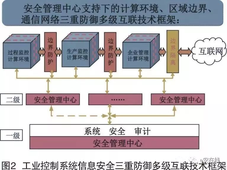
(1) Triple Protection Multi-Level Interconnection Technical Framework
The design of the level protection scheme for industrial control systems refers to the previously constructed triple defense system supported by the security management center, which includes a computing environment, area boundaries, and communication networks. It adopts a zoned architecture, considering the complex and diverse bus protocols of industrial control systems, strong real-time requirements, limited node computing resources, high reliability requirements of devices, short fault recovery times, and security mechanisms that do not affect real-time performance, to achieve trusted, controllable, and manageable system security interconnection, area boundary security protection, and computing environment security, as shown in Figure 2.
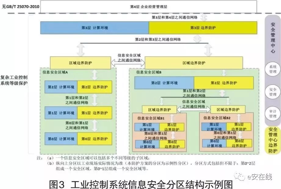
(2) Security Zoning Deep Defense Strategy
For complex industrial control systems, it is recommended to use a layered and zoned protection structure to implement information security level protection design, while for simple industrial control systems, information security level protection design should be conducted without layering. Based on the nature of the business objects being protected in industrial control systems, zoning should be implemented according to the technical characteristics of functional levels to conduct security protection for industrial control systems.
According to Figure 1, the industrial control system is vertically divided into five layers, where Levels 0 to 3 fall within the scope of industrial control systems’ level protection, which is the area covered by this protection scheme; horizontally, the industrial control system is divided into security zones based on the importance, real-time nature, relevance, impact on the controlled field devices, functional scope, and asset attributes of the business. Different security protection zones are formed, and all systems must be placed within their respective security zones, with specific zoning based on the actual situation of the industrial site. This revision provides an exemplary zoning for the protection scheme, which includes but is not limited to: Levels 0 to 2 forming one security zone, Levels 0 to 1 forming one security zone, and different security zones within the same layer, as shown in Figure 3.
The main basis for zoning includes the real-time nature of the business system or its functional modules, users, main functions, equipment usage locations, interrelations between various business systems, wide area network communication methods, and the degree of impact on industrial control systems. For additional security and reliability requirements, the main security zones can also be further subdivided into sub-zones based on operational functions. Dividing devices into different zones can help enterprises effectively establish a “deep defense” strategy. Control functions of various systems with the same functions and security requirements are divided into different security zones, and network segment addresses are allocated to each security function area according to the principle of convenient management.
3. Design of Security Protection System for Industrial Control Systems
Level protection is divided into four levels, with progressively enhanced protection scheme designs. However, the protection categories in the protection scheme design are the same, differing only in the intensity of the security protection design. The protection categories include: secure computing environment, security area boundaries, secure communication networks, and security management centers. The design of the information security protection environment for each level of industrial control systems is realized by designing the secure computing environment, security area boundaries, secure communication networks, and security management centers.
(1) Design Goals and Strategies
The design goals of level protection for industrial control systems progressively enhance. The design goal of the information security protection environment for Level 1 industrial control systems is to achieve autonomous access control of the classified system’s information security protection system, enabling system users to have self-protection capabilities over their owned objects. The design goal of the information security protection environment for Level 2 industrial control systems is to add security functions such as system security auditing based on Level 1 and implement role-based access control for stronger security protection capabilities. The design goal of the information security protection environment for Level 3 industrial control systems is to enhance identity verification, auditing, and other functions on the basis of Level 2 while adding secure communication measures between area boundaries. The design goal of the information security protection environment for Level 4 industrial control systems is to elaborate on the security protection design requirements for key control loops, requiring designers to provide protection methods and security strategies suitable for industrial control application characteristics in risky situations, achieving high-intensity protection for sensitive resources under unified security policy management through measures such as implementing role-based access control and enhancing the system’s auditing mechanism.
The design strategies for level protection in industrial control systems progressively enhance. The design strategy for the security protection environment of Level 1 systems is based on identity verification, implementing access control according to the objects of industrial control systems. The monitoring layer and control layer provide autonomous access control for operator stations and engineering stations’ files and database tables based on users and/or user groups to achieve isolation between users and data. The device layer implements autonomous access control for security and protection systems, configuration data, and configuration files based on users and/or user groups, enabling users to have self-security protection capabilities; area boundary protection is provided through packet filtering and state detection; data integrity protection and system integrity protection are provided through data verification and malicious code prevention measures. The design strategy for the information security protection environment of Level 2 industrial control systems is based on identity verification, providing autonomous access control for individual users and/or user groups regarding shared files, database tables, and configuration data; area boundary protection is provided through packet filtering and state detection; data integrity and confidentiality protection is enhanced through system security auditing and other functions, making users responsible for their actions. The design strategy for the information security protection environment of Level 3 industrial control systems is to correspondingly enhance identity verification and auditing functions based on Level 2 and increase security communication protection between boundaries to ensure boundary security. The design strategy for the information security protection environment of Level 4 industrial control systems is to construct a role-based access control model based on Level 3, indicating the classification of subjects and objects and the combination of non-level classifications, and to implement access control for subjects and their objects based on role-based access control rules.
(2) Key Design Technical Requirements
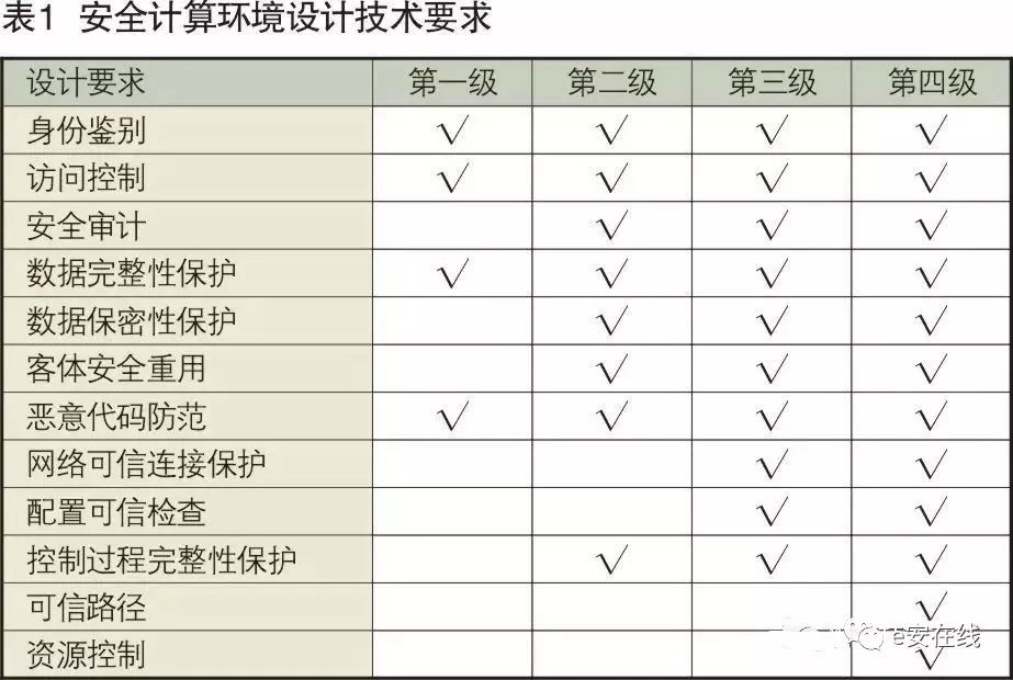
1. Technical Requirements for Secure Computing Environment Design
The secure computing environment includes the relevant components for information storage, processing, and implementing security policies within Levels 0 to 3 of industrial control systems. The secure computing environment is classified into Level 1, Level 2, Level 3, and Level 4 secure computing environments based on protection capabilities, with progressively enhanced technical requirements for secure computing environment design at each level, as shown in Table 1.
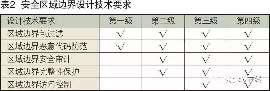
2. Technical Requirements for Security Area Boundary Design
The security area boundary refers to the boundary of the secure computing environment of the classified system and the relevant components that connect and implement security policies between the secure computing environment and secure communication networks. The security area boundary is classified into Level 1, Level 2, Level 3, and Level 4 security area boundaries based on protection capabilities, with progressively enhanced technical requirements for security area boundary design at each level, as shown in Table 2.
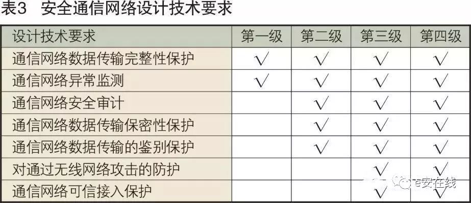
3. Technical Requirements for Secure Communication Network Design
The secure communication network refers to the relevant components that transmit information between the secure computing environment and the information security area of the classified system and implement security policies. The secure communication network is classified into Level 1, Level 2, Level 3, and Level 4 secure communication networks based on protection capabilities, with progressively enhanced technical requirements for secure communication network design at each level, as shown in Table 3.
Protection of network communication, such as the process of configuration download to the controller from the engineer’s station, is conducted through the network. If there are unsafe factors in the network, anti-tampering protection must be added. First, it is necessary to verify whether the operator of the engineer’s station has the permission to perform the download operation on the controller. If there is permission, a communication connection between the engineer’s station and the controller can be established.
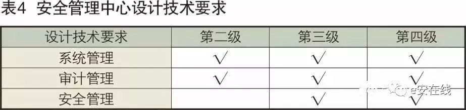
4. Technical Requirements for Security Management Center Design
The security management center refers to the platform that implements unified management of security policies and security mechanisms on the secure computing environment, security area boundaries, and secure communication networks of the classified system. Security management centers need to be established for Level 2 and above classified system security protection environments, referred to as Level 2, Level 3, and Level 4 security management centers. The design technical requirements for security management centers progressively enhance, with requirements at each level as shown in Table 4.
5. Analysis of Security Design Technical Requirements Based on the Characteristics of Industrial Control Systems
① Implementing Security Protection Based on the Characteristics of Control System Business Processes
The computing environment of industrial control systems, particularly those at Levels 0, 1, and 2, is quite special. The controllers (or PLCs, RTUs in SCADA) at Level 1 are connected to sensors and actuators through field buses, forming a control loop, which is a fundamental and critical part of industrial control systems and an important protection target. The control logic of the controller’s operating system is also a key link connecting Levels 0 and 2. Access and operation of the controller must first go through identity verification. This includes configuration downloads at the engineer’s station and commands issued from the operator’s station, which must be authorized after identity verification. In the past, some controllers performed identity verification for configuration downloads at the engineer’s station through configuration software systems, verifying identity before executing commands issued from the operator’s station to the controller, providing protection against spoofing attacks.
② Integrity Protection of Control Processes
This is to prevent interference and damage to the data transmission and processing of the control loop, preventing data delays, losses, and tampering, and protecting the control system’s synchronization mechanism and time calibration mechanism. The controller, from the perspective of its computing environment, is easily affected by interference from the network, field bus, and I/O ports, such as but not limited to the following behaviors:
a) An excessive number of interrupt requests within a control cycle;
b) ICMP protocol requests exceeding reasonable packet rate ranges;
c) Broadcast messages exceeding reasonable packet rate ranges;
d) Requests that disrupt the request-response mechanism of the field bus;
e) Disruption of redundancy mechanisms;
f) Interference with the normal operation of voting systems and other security protection systems;
g) Maliciously triggering redundant system switches and disabling security protection systems;
h) Other interferences.
Such interferences can disrupt the execution of control tasks, potentially causing the controller to reset, and these malicious attacks can appear with legitimate identities. Therefore, the design of control application systems must be able to identify, monitor, and protect against such attack behaviors, which can be implemented at the computing environment level, such as preventing the closure of attacked ports on the controller, filtering such attacks at the boundary, and adopting protection measures against spoofing, tampering, and interference in communication to form a multi-layered deep defense.
③ Security Protection of Field Buses
Security issues of field buses and field device layers can be avoided under physical protection or human monitoring. In the field bus and field devices, physical interfaces that can be inserted or modified should be avoided. Some devices are equipped with HART interfaces, which can provide opportunities for unauthorized access and parameter modifications in environments lacking physical protection and monitoring. Real-time monitoring should be implemented at the field bus interface of the controller, with timely alerts for frame losses, abnormal data, and excessive jitter. For important field buses and devices, integrity or confidentiality protection should be implemented using cryptographic techniques suitable for real-time processing with small bit sizes based on application protection needs.
④ Using Operator Station to Send Commands to Controller as an Example
Using the operator station to send commands to the controller illustrates the security protection measures required along this information processing path. Before starting, the operator station measures the operating system loader and operating system using trusted computing processors, comparing it with stored message digest values. If no tampering is found, the system starts, and applications and services confirmed by the security management center as belonging to the whitelist are initiated. The operator logs into the operator station, using a U-KEY for identity verification inserted into the USB interface of the operator station. At this point, all external device ports of the operator station are disabled. This insertion event reports to the security management center, which verifies and confirms the operator’s identity and authorization. After this, the operator does not need to perform identity verification for subsequent operations to ensure real-time responses. When the operator leaves the station, a clear logout operation must be performed, and the U-KEY must be removed. For security reasons, if the operator station has not been operated for a certain period, it should prompt the operator to continue. If there is no response, the screen should be locked promptly to terminate the session and prevent impersonation. Unlocking requires entering a password. The entire process is audited and can be traced by the security management center. During communication with the controller, identity verification must be performed first; only after passing identity verification can a communication connection be established. Important commands and data transmissions should use cryptographic techniques to ensure integrity or confidentiality, preventing forgery of commands and data deception. The communication session between the operator station and the controller should also be protected, maintaining the validity of the session during operator handovers and considering the ability to respond in real-time during emergencies. Auditing measures should clearly define the actions and responsibilities of the operator.
Conclusion
The content of the security design requirements for industrial control systems added to GB/T 25070 is a revision based on the national standard GB/T25070-2010 to adapt to new technologies and applications in industrial control, establishing a unified standard for industrial control system level protection and creating an overall security protection system and framework. It provides detailed and implementable security design requirements that can guide operational units and information security service organizations in designing security technical solutions for level protection, effectively responding to information security threats targeting industrial control system environments, protecting national industrial control systems from illegal attacks, and ensuring the normal operation of important industrial control systems, thereby safeguarding the nation’s industrial infrastructure from damage.
Source: e安在线