Industrial robots consist of three basic components: the main body, the drive system, and the control system.
The main body includes the base and the actuators, which consist of the arm, wrist, and hand; some robots also have locomotion mechanisms. Most industrial robots have 3 to 6 degrees of freedom, with the wrist typically having 1 to 3 degrees of freedom.
The drive system includes the power unit and transmission mechanism, which enable the actuators to perform corresponding actions.
The control system issues command signals to the drive system and actuators according to the input program and performs control.
Today, let’s first discuss the control system!
1. Functions Achieved by Industrial Robot Control Systems
The robot control system is an important component of the robot, used for controlling the operation machine to complete specific work tasks. Its basic functions are as follows:
-
Memory function: stores operation sequences, motion paths, motion modes, motion speeds, and information related to production processes.
-
Teaching function: offline programming, online teaching, indirect teaching. Online teaching includes teaching box and guided teaching.
-
Peripheral device communication function: input and output interfaces, communication interfaces, network interfaces, synchronization interfaces.
-
Coordinate setting function: four coordinate systems related to joints, absolute, tool, and user-defined. Human-machine interface: teaching box, operation panel, display.
-
Sensor interface: position detection, vision, touch, force sensing, etc.
-
Position servo function: multi-axis linkage, motion control, speed and acceleration control, dynamic compensation, etc.
-
Fault diagnosis and safety protection function: monitoring system status during operation, safety protection under fault conditions, and fault self-diagnosis.
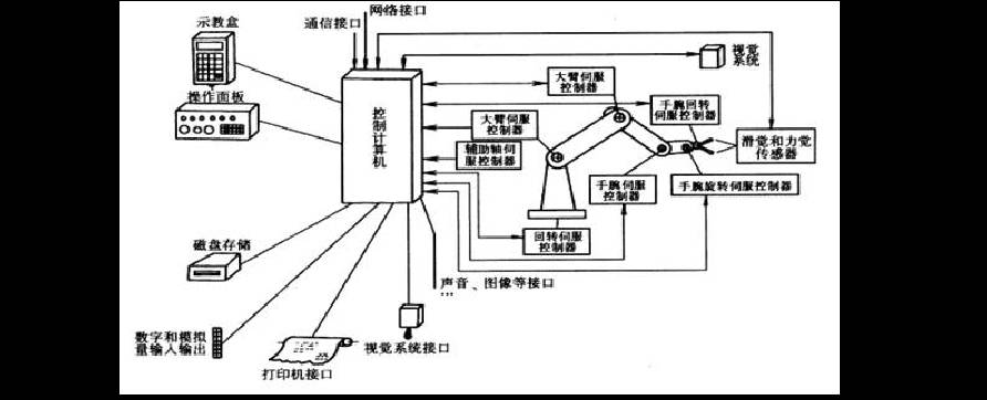
Figure 1 Robot Control System Composition Diagram
(I searched the entire internet and really couldn’t find a clearer picture )
)
2. Components of Industrial Robot Control Systems
-
Control computer: the scheduling and command institution of the control system. Generally, it is a microcomputer or microprocessor with 32-bit, 64-bit, etc., such as Pentium series CPUs and other types of CPUs.
-
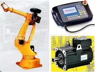
Teaching box: teaches the robot’s working trajectory and parameter settings, as well as all human-computer interaction operations, possessing its own independent CPU and storage unit, and exchanges information with the main computer via serial communication.
-
Operation panel: consists of various operation keys and status indicator lights, only completing basic functional operations.
-
Hard disk and floppy disk storage: peripheral storage for storing robot working programs.
-
Digital and analog input/output: input or output of various status and control commands.
-
Printer interface: records various information that needs to be output.
-
Sensor interface: used for automatic detection of information, achieving robot compliant control, generally including force, touch, and vision sensors.
-
Axis controller: completes the control of the position, speed, and acceleration of each joint of the robot.
-
Auxiliary device control: used for controlling auxiliary devices that cooperate with the robot, such as gripper positioners.
-
Communication interface: enables information exchange between the robot and other devices, generally including serial interfaces, parallel interfaces, etc.
-
Network interface:① Ethernet interface: allows direct PC communication with multiple or single robots via Ethernet, with data transmission rates up to 10 Mbit/s, and supports TCP/IP communication protocol after programming applications on PC using Windows library functions, loading data and programs into various robot controllers through Ethernet interface.
② Fieldbus interface: supports various popular field bus specifications, such as DeviceNet, AB Remote I/O, Interbus-S, Profibus-DP, M-NET, etc.
3. Classification of Industrial Robot Control Systems
-
Program control system: applies a certain pattern of control to each degree of freedom, allowing the robot to achieve the required spatial trajectory.
-
Adaptive control system: adjusts the parameters of a nonlinear model based on the observation of the operating machine’s state and servo errors when external conditions change, to ensure the required quality or to improve control quality with experience, until the error disappears. This system’s structure and parameters can change automatically over time and conditions.
-
Artificial intelligence system: cannot pre-program motion procedures, but requires real-time determination of control actions based on the surrounding state information obtained during motion.
Motion modes:
Point-type: requires the robot to accurately control the end effector’s pose, regardless of the path;
Trajectory type: requires the robot to move according to the taught trajectory and speed.
Control bus: International standard bus control system. Uses international standard buses as the control bus for the control system, such as VME, MULTI-bus, STD-bus, PC-bus.
Custom bus control system: uses a bus defined by the manufacturer as the control system bus.
Programming methods: physical setting programming system. The operator sets fixed limit switches to realize the start and stop program operations, suitable only for simple pick-and-place tasks.
Online programming: completes the memory process of operational information through human teaching, including direct teaching (hand-on teaching), simulated teaching, and teaching box teaching.
Offline programming: does not directly teach the robot in the actual working environment, but generates teaching programs by using advanced robot programming languages, remotely generating robot working trajectories.
4. Structure of Robot Control Systems
Robot control systems can be divided into three categories based on their control methods.
-
1. Centralized control system: implements all control functions using one computer, with a simple structure and low cost, but poor real-time performance and difficulty in expansion. This structure was commonly used in early robots.
In PC-based centralized control systems, the open characteristics of PC resources are fully utilized to achieve good openness: various control cards, sensor devices, etc., can be integrated into the control system through standard PCI slots or standard serial and parallel ports.
The advantages of centralized control systems include: lower hardware costs, ease of information collection and analysis, easier implementation of optimal control, and better integrity and coordination. The hardware expansion of PC-based systems is relatively convenient.
The disadvantages are also evident: the system control lacks flexibility, control hazards are easily centralized, and once a fault occurs, its impact is wide and the consequences are severe; due to the high real-time requirements of industrial robots, when the system performs a large amount of data calculations, it will reduce system real-time performance, and the system’s response capability to multiple tasks may conflict with the system’s real-time performance; in addition, the complex wiring of the system may reduce its reliability.
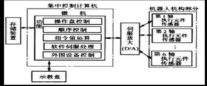
Figure 2 Centralized Control System Diagram
-
2. Master-slave control system: uses master and slave processors to achieve all control functions of the system. The master CPU manages, performs coordinate transformations, trajectory generation, and system self-diagnosis; the slave CPU controls the movements of all joints. Its composition diagram is shown in Figure 3. The master-slave control system has better real-time performance, suitable for high-precision and high-speed control, but has poor system expandability and maintenance difficulties.
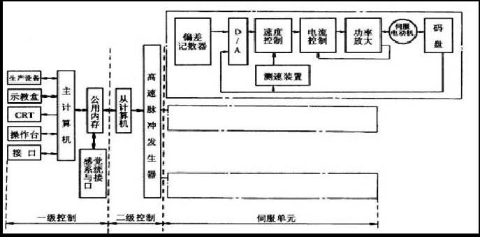
Figure 3 Master-slave Control System Diagram
3. Distributed control system: divides the system control into several modules based on the nature and method of the system, where each module has different control tasks and strategies. The modes can be in a master-slave relationship or an equal relationship. This method has good real-time performance, is easy to achieve high-speed and high-precision control, and is easy to expand. It can achieve intelligent control and is currently a popular method, with its control diagram shown in Figure 4.
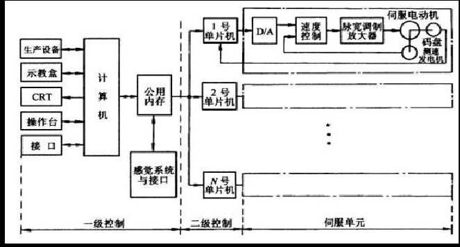
Figure 4 Distributed Control System Diagram
The main idea is “distributed control, centralized management,” meaning the system can coordinate and allocate its overall goals and tasks, and complete control tasks through the coordinated work of subsystems. The entire system is decentralized in functionality, logic, and physically, so the DCS system is also known as a distributed control system.
In this structure, the subsystems consist of controllers and different controlled objects or devices, and the subsystems communicate with each other through networks, etc. The distributed control structure provides an open, real-time, precise robot control system. Distributed systems often use a two-level control method.
The two-level distributed control system usually consists of an upper computer, a lower computer, and a network. The upper computer can perform different trajectory planning and control algorithms, while the lower computer conducts research and implementation of interpolation, control optimization, etc. The upper and lower computers coordinate their work through communication buses, which can take forms such as RS-232, RS-485, IEEE-488, and USB buses.
Now, with the development of Ethernet and fieldbus technology, robots are provided with faster, more stable, and effective communication services. Especially the fieldbus, which is applied in the production site, enabling bidirectional multi-node digital communication between microcomputer-based measurement and control devices, thus forming a new type of network-integrated distributed control system—Fieldbus Control System (FCS).
In factory production networks, devices that can be connected via fieldbus are collectively referred to as “field devices/instruments.” From a system perspective, industrial robots, as one of the factory production devices, can also be classified as field devices.
After introducing fieldbus technology into robot systems, it is more conducive to the integration of robots in industrial production environments.
The advantages of distributed control systems include: good system flexibility, reduced danger of control systems, decentralized control with multiple processors, facilitating parallel execution of system functions, improving system processing efficiency, and shortening response times.
For industrial robots with multiple degrees of freedom, centralized control handles the coupling relationship between each control axis well, allowing for simple compensation. However, when the number of axes increases to the point where control algorithms become complex, its control performance deteriorates. Additionally, when the number of axes or control algorithms in the system becomes complex, it may lead to a redesign of the system. In contrast, each motion axis in a distributed structure is handled by a controller, meaning the system has less inter-axis coupling and higher system reconstructability.
▶ Source: Edited and compiled from online materials about industrial robots, uploaded by fzf118.
▶ The editor thinks you might also like these :
:
From a million employees to a million robots, to darkened workshops, what has this company experienced?
A mechanical arm extending from under a girl’s skirt, what the heck!