Abstract:
NB-IoT is an emerging cellular technology that better supports applications requiring large connections, low power consumption, low throughput, low device costs, and high latency tolerance. Compared to LTE systems, the random access channel NPRACH in the NB-IoT system has been redesigned. A detailed analysis of the structural design of NPRACH in the NB-IoT system is provided through a comparison with the LTE system, and a 2-D FFT-based NPRACH receiver detection algorithm is proposed. Simulation analysis using MATLAB shows that under different coverage levels, the algorithm detects the NPRACH Preamble miss detection probability (MDP) to be below 0.05% and the false alarm probability (FAP) to be below 0.1%, both meeting the standard requirements of 1% MDP and 0.1% FAP, with a probability of time-of-arrival (ToA) error within the range of -2.5 to 2.5 μs exceeding 95%.
Chinese Citation Format: Li Xiaowen, Qu Yuanyuan, Zhou Shuqi, et al. NB-IoT Physical Layer Random Access Analysis and Receiver Detection Algorithm[J]. Application of Electronic Technique, 2018, 44(9): 99-103.English Citation Format: Li Xiaowen, Qu Yuanyuan, Zhou Shuqi, et al. NB-IoT Physical Random Access Analysis and Receiver Detection Algorithm[J]. Application of Electronic Technique, 2018, 44(9): 99-103.
0 Introduction
The rapid development of Internet of Things (IoT) technology has led to the rise of Low Power Wide Area (LPWA) technologies, such as LoRa (Long Range), Sigfox, INGE, TELENSA, etc.[1-2] However, these protocols cannot serve established wireless local area networks and wide area networks, such as WiFi, ZigBee, and LTE.[3] The 3rd Generation Partnership Project (3GPP) introduced a cellular LPWA solution for ultra-low complexity and low throughput IoT applications—a NarrowBand Internet of Things (NB-IoT) based on authorized spectrum.[4-5] It features low cost, low power consumption, large connections, and wide coverage. This paper analyzes the differences between LTE and NB-IoT to conclude the necessity of a new design for the NarrowBand Physical Random Access Channel (NPRACH) structure[6-9] and NPRACH Preamble[10-11], proposing a joint estimation algorithm for time-of-arrival (ToA) and carrier frequency offset (CFO) based on the 2-D discrete Fourier transform (2-D FFT), followed by simulation analysis using a maximum correlation threshold detection method.
1 Analysis of Main Differences Between LTE and NB-IoT
This section introduces and analyzes the technical changes brought by the capability differences and coverage level requirements between LTE and NB-IoT.
1.1 Comparison of Capability Differences Between NB-IoT and LTE
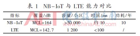
For services such as smart water meters, in addition to characteristics such as low data volume, low rate requirements, insensitivity to transmission delay, and a large number of terminals, NB-IoT also requires high coverage capability, ability to meet harsh environments, low terminal costs, and long standby times. Therefore, the capability differences between NB-IoT and LTE are summarized in Table 1. Among them, MCL (Maximum Coupling Loss) is the maximum coupling loss.
1.2 Technical Differences Brought by Coverage Level Requirements
NB-IoT uses channel narrowing to enhance transmission power spectral density, and employs redundancy coding and GAP mechanisms to improve decoding success rates.
(1) Narrowband Technology: In an independently deployed manner, the NB-IoT downlink bandwidth is only 1/100 of 20 MHz, and under the same transmission power conditions, the power spectral density increases by about 20 dB. Upstream: The minimum single-carrier bandwidth is 3.75 kHz, which increases the power spectral density by approximately 37 dB compared to 20 MHz LTE terminals.
(2) Redundancy Coding Technology: To meet NB-IoT coverage level requirements, redundancy coding technology is introduced to increase the success rate of single random access.
(3) GAP Mechanism: In the downlink, NB-IoT adopts a unique DL GAP mechanism[12], allowing only other terminals to send data during the GAP period, thus ensuring fairness and resource utilization. In the uplink, to suppress the impact of temperature changes on crystal oscillator frequency offset[13], which leads to reduced data transmission efficiency, NB-IoT introduces UL GAP. The GAP switches to the downlink, utilizing NB-IoT downlink signal synchronization tracking and time-frequency offset compensation[6,14-15].
2 Specific Design and Analysis of NB-IoT NPRACH
This section provides a detailed analysis of the NPRACH channel structure and random access Preamble sequence design scheme for NB-IoT.
2.1 Channel Structure
The basic unit of Preamble transmission consists of 4 symbol groups, each containing 1 cyclic prefix (CP) and 5 identical symbols, as shown in Figure 1.
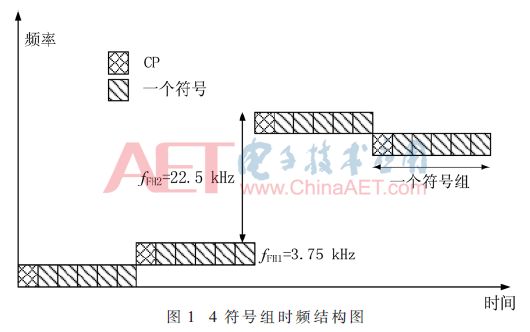
Since the signals sent within each symbol group are identical, it ensures orthogonality between multiple NPRACH channels configured in the frequency domain, thus eliminating the need to configure guard bandwidth between NPRACH channels.
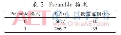
In NB-IoT, two Preamble formats are defined[8], as shown in Table 2, which facilitates flexibility in cell coverage.
Additionally, the Preamble supports Q times of repeated transmission, where the value of Q is configured by the Radio Resource Control (RRC) sublayer of the protocol stack[16]. When Q is greater than 1, the first subcarrier index is randomly chosen by the UE from the available subcarrier set, and the subcarrier index of the first symbol group of the remaining Q-1 symbol groups is increased by a random jump variable based on the first subcarrier index of the first 4 symbol group. The subcarrier index corresponding to the ith symbol group is shown in Equation (1):
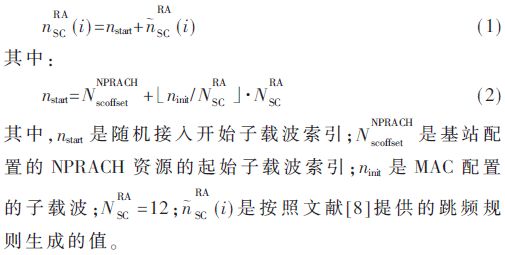
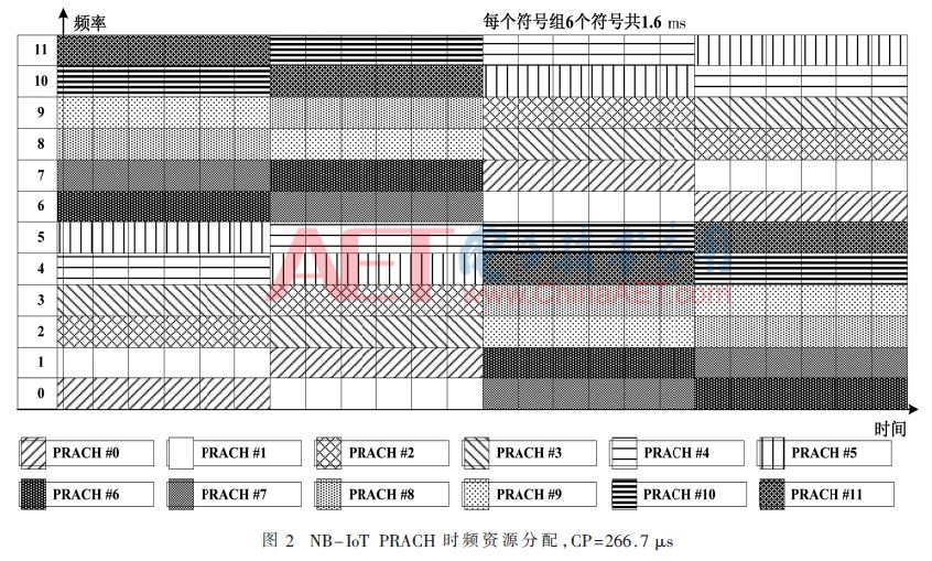
By calculation, all symbol groups are restricted within a NPRACH band containing 12 subcarriers. Figure 2 illustrates the subcarrier allocation diagram for 4 symbol groups when the Preamble format is 1.
2.2 Sequence Structure
The design of the narrowband IoT preamble sequence completely abandons the original design scheme, sending the same symbol across all symbol groups, resulting in a waveform with a constant envelope, allowing all UEs to transmit NPRACH signals with high energy efficiency, even under fully saturated power amplifiers, without spectral growth or error vector magnitude (EVM) degradation.
3 Receiver Detection Algorithm Based on 2-D FFT
This section employs a maximum correlation threshold detection method and proposes an algorithm for joint estimation of ToA and residual CFO based on 2-D FFT.
3.1 Random Access Preamble Signal Received by the Base Station
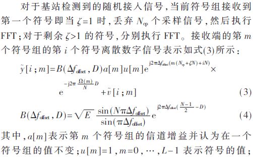
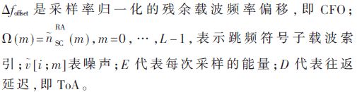
For the random access signal detected by the base station, when the current symbol group receives the first symbol, i.e., when ζ=1, Ncp samples are discarded, and FFT is executed. For the remaining ζ>1 symbols, FFT is executed separately. The discrete digital signal of the ith symbol group at the receiver is represented as shown in Equation (3):
3.2 Joint Estimation of (ToA, CFO)
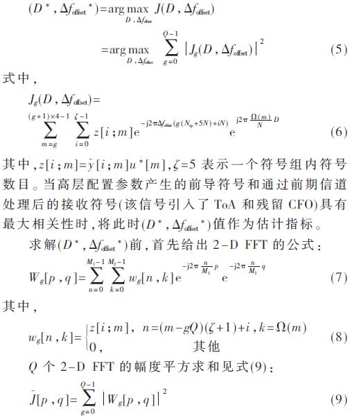
Assuming the channel environment remains unchanged in each basic transmission block, i.e., 4 symbol groups, ToA and residual CFO can be jointly estimated as shown in Equation (5):
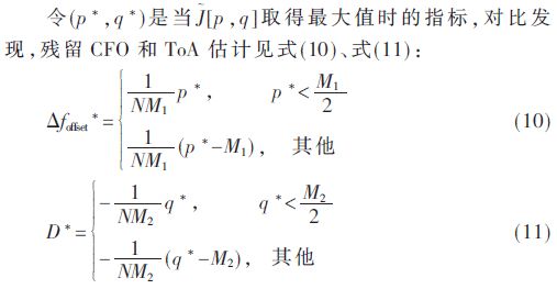
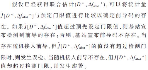
3.3 Preamble Detection
4 Simulation Implementation and Performance Analysis
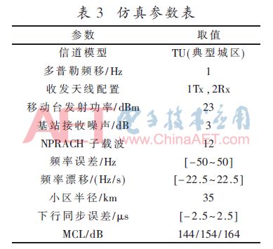
The simulation parameters used in this section are shown in Table 3.
The specific process of the link-level simulation is as follows:
(1) The transmitter selects a time-frequency resource and preamble format from the configured NPRACH indication, mapping the generated preamble symbols onto the OFDM resource grid according to the relevant calculation formulas.
(2) The transmitter performs inverse FFT to obtain time-domain sampled signals and inserts CP accordingly.
(3) The transmitter generates random access signals by up-converting and filtering the time-domain samples.
(4) The random access signals are transmitted over the wireless channel using the transmission power.
(5) White Gaussian noise is added to the channel to simulate a real channel environment.
(6) The receiver filters and down-converts the received signals.
(7) For each received symbol group in the preamble, the receiver discards CP samples and performs FFT on the remaining samples.
(8) The receiver performs joint ToA and residual CFO estimation and compares it with a preset threshold to determine the presence of the preamble. For false alarm testing, since the input to the receiver is a Gaussian noise signal, the above steps (1) to (4) are not necessary.
The CDF of ToA Error estimation is shown in Figure 3. From Figure 3, it can be seen that as the coverage level increases, i.e., the environment becomes harsher, the estimated performance decreases, but the three curves are very close, indicating good estimation performance under different coverage levels. Statistical data obtained from 10,000 repeated experiments is summarized in Table 4.
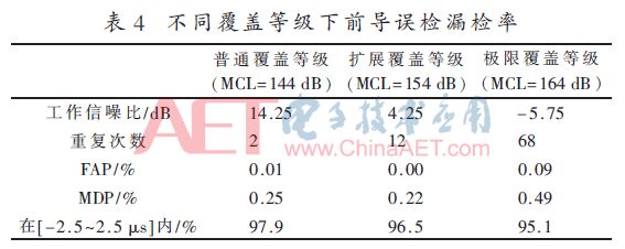

Table 4 summarizes the FAP, MDP, and the probability of ToA within the confidence interval [-2.5~2.5 μs] under three coverage levels of the NPRACH design. It can be seen that the preamble still meets the standard detection performance requirements for NPRACH under extreme coverage levels, i.e., MDP not exceeding 1% and FAP not exceeding 0.1%.
The standard stipulates that when ToA Error does not exceed 3.646 μs, it is considered correctly estimated. The simulation results indicate that the ToA Error is within the standard range, with a probability exceeding 95% in the range of [-2.5~2.5 μs], demonstrating a very high confidence level. Increasing coverage levels leads to an increase in ToA Error, but the reduction within the confidence range of [-2.5~2.5 μs] does not exceed 3%. Compared to traditional LTE systems, the accuracy requirements for ToA Error estimation are relaxed for NB-IoT Preamble, thus even under extreme coverage levels, it can still meet the needs of NB-IoT.
5 Conclusion
This paper compares the main differences between traditional LTE systems and NB-IoT systems, detailing the design scheme and principles of NPRACH based on single-carrier group hopping sequences. Through the proposed 2-D FFT-based algorithm for joint estimation of (ToA, CFO) and the maximum correlation threshold detection method for preamble detection, it is analyzed that under this receiver detection algorithm, the NB-IoT system meets the requirements set by the standards in all three coverage levels, demonstrating good performance. An excellent receiver detection algorithm can achieve more accurate ToA estimation and improve detection accuracy, thus the NPRACH receiver detection algorithm may be an important research point in future work.
References
[1] POP A I, RAZA U, KULKARNI P, et al. Does bidirectional traffic do more harm than good in LoRaWAN based LPWA networks?[C]. Submitted to IEEE GLOBECOM. IEEE, 2017.
[2] RAZA U, KULKARNI P, SOORIYABANDARA M. Low power wide area networks: an overview[J]. IEEE Communications Surveys & Tutorials, 2016, 19(2): 855-873.
[3] YANG W, WANG M, ZHANG J, et al. Narrowband wireless access for low-power massive Internet of Things: a bandwidth perspective[J]. IEEE Wireless Communications, 2017, 24(3): 138-145.
[4] ANTEUR M, DESLANDES V, THOMAS N, et al. Ultra narrowband technique for low power wide area communications[C]. GLOBECOM 2015-2015 IEEE Global Communications Conference. IEEE, 2014: 1-6.
[5] RICO-ALVARINO A, VAJAPEYAM M, XU H, et al. An overview of 3GPP enhancements on machine to machine communications[J]. IEEE Communications Magazine, 2016, 54(6): 14-21.
[6] QUALCOMM. On UL gaps for frequency error correction[R]. RAN4 #79, R4-164246, Nanjing, China, 2016.
[7] Ericsson. Narrowband IoT-random access design[R]. RAN1 #83, R1-157424, Anaheim, US, 2015.
[8] Technical specification group radio access network; evolved universal terrestrial radio access(E-UTRA); physical channels and modulation; release 13[S]. 3GPP TS 36.211 V13.3.0, 2016.
[9] ZTE. Single-tone PRACH for NB-IoT[R]. RAN1 #84, R1-160482, St Julian’s, Malta, 2016.
[10] LG. Single-tone random access procedure for NB-IoT[R]. RAN1 #84. R1-160622, St Julian’s, Malta, 2016.
[11] Huawei. NB-PRACH design[R]. RAN1 NB-IoT Ad-Hoc #2, R1-161812, Sophia-Antipolis, France, 2016.
[12] Ericsson. NB-IoT-search space design considerations[R]. RAN1 NB-IOT Ad Hoc#2, R1-161822, Sophia Antipolis, France, 2016.
[13] Sony. NB IoT UL transmission period and transmission gaps[R]. RAN4 #79, R4-164201, Nanjing, China, 2016.
[14] Huawei. UL transmission gap[R]. RAN4#79, R4-164008, Nanjing, China, 2016.
[15] Intel. Simulation results of UCG parameters for NB-IoT[R]. RAN4 #79, R4-163255, Nanjing, China, 2016.
[16] Technical specification group radio access network; evolved universal terrestrial radio access(E-UTRA); medium access control(MAC) protocol specification; release 13[S]. 3GPP TS 36.321 V13.3.0, 2016.
Author Information:
Li Xiaowen, Qu Yuanyuan, Zhou Shuqi, Mou Hongyan, Chen Qirong
(Chongqing University of Posts and Telecommunications, School of Communication and Information Engineering, Chongqing 400065)
Recruitment Information