The embedded audio system is widely used in embedded fields such as GPS navigation, PDAs, and 3G mobile phones. However, there is currently little research in this area in China. The audio system design includes both software and hardware design, with a hardware architecture based on the IIS bus. IIS (Inter-IC Sound bus), also known as I2S, is a serial digital audio bus protocol proposed by Philips. Many audio chips and MCUs currently provide support for IIS. On the software side, as a complex embedded system, it requires an embedded operating system to support it. Linux is an open-source UNIX-like system, and due to its kernel modularity and support for various embedded processors including ARM and PPC, it is widely used in high-end embedded products. Although Linux provides numerous APIs to reduce the complexity of driver creation, the high real-time requirements of audio applications and the large amount of data that needs to be processed necessitate reasonable resource allocation and the use of appropriate algorithms. This paper constructs an audio system based on IIS for Samsung’s S3C44B0 ARM processor and introduces the driver construction technology for this audio system based on the Linux 2.4.0 kernel.
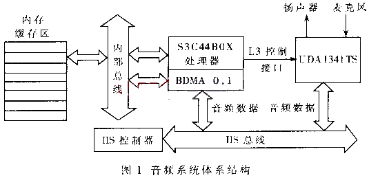
1 Hardware Architecture The IIS bus only handles sound data. Other signals (such as control signals) must be transmitted separately. To minimize the number of pins on the chip, IIS uses only three serial buses. These three lines are: the data line that provides time-division multiplexing functionality, the field select line (channel selection), and the clock signal line. In Samsung’s ARM chip, to achieve full-duplex mode, two serial data lines are used, one for input and one for output. Additionally, Samsung’s IIS interface provides three data transmission modes: • Normal transmission mode. This mode is based on FIFO registers. In this mode, the CPU accesses the FIFO register through polling and controls the FIFO through the seventh bit of the IISCON register. • DMA mode. This mode is an external device control mode. It uses bus stealing to exchange data between external devices and main memory, thereby improving system throughput. Samsung’s ARM chip has four channel DMA controllers to control various external devices, with IIS sharing two bridged DMA (BDMA) channels with other serial peripherals. By setting the IISFCON register of the CPU, the IIS interface can operate in DMA mode. In this mode, the control of the FIFO register group is in the hands of the DMA controller. When the FIFO is full, the DMA controller processes the data in the FIFO. The selection of DMA mode is controlled by the fourth and fifth bits of the IISCON register.
• Transmission/Reception mode. In this mode, the IIS data line simultaneously receives and sends audio data through dual-channel DMA. This system uses this data transmission mode. Figure 1 is a schematic diagram of the connection between the 44BOX chip and Philips’ UDA1341TS audio chip. In this architecture, to achieve full-duplex, data transmission uses two BDMA channels. The data transmission (for playback as an example) first goes from the internal bus to memory, then to the BDMA controller channel 0, and is subsequently written to the IIS bus and transmitted to the audio chip. Channel 1 is used for recording. Samsung’s BDMA controller does not have a built-in storage area, so the driver must allocate a DMA buffer for the audio device. The address of the buffer is set in the address register of the channel DMA controller. The UDA1341TS chip provides not only the IIS interface and microphone/speaker interface but also the L3 interface for volume control and so on. The L3 interface connects to three general data output pins on the S3C44B0. 2 Audio Device Low-Level Software Design The variety of hardware devices in embedded systems is extensive, and there is a lack of standard architecture found in PCs, so drivers must be written for various devices. The main task of the driver is to control the flow of audio data in hardware and to provide a standard interface for audio applications. Given the limited resources of embedded systems and the limited power of processors, reasonable resource allocation is a challenge in the design of audio device drivers. It should be noted that in Samsung’s ARM chip, the registers for I/O devices are part of the memory space, and ordinary memory access statements can be used to read and write I/O registers, thus controlling external devices. This is the biggest difference between this embedded system and traditional PCs based on Intel processors. 2.1 Driver Function The tasks that need to be completed in the device driver include: initializing and releasing the device and corresponding resources; reading data sent to the device file from the application program and returning the requested data to the application program. This requires data transfer between user space, kernel space, the bus, and peripherals. 2.2 Driver Architecture In Linux device drivers, audio devices are classified by function, with each type corresponding to a different driver. The UDA1341TS audio chip provides the following functions:
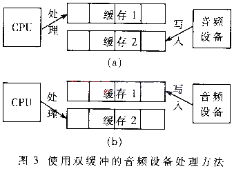
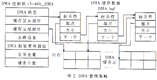
• Digital audio. This function is sometimes referred to as DSP or Codec device. Its function is to play digital sound files or record sound. • Mixer. Used to control the volume of various inputs and outputs, corresponding to the L3 interface in this system. In Linux device drivers, devices are treated as files, and in the driver, function pointers in the structure file_operations are bound to the corresponding routine functions of the driver to achieve operations on logical files by the virtual file system (VFS). The device files corresponding to digital audio devices (audio) and mixers (mixer) are /dev/dsp and /dev/mixer, respectively. 2.3 Device Initialization and Unloading The driver design for /dev/dsp mainly includes: device initialization and unloading, memory and DMA buffer management, implementation of device-independent operations (routines), and interrupt handling. During device initialization, the relevant registers of the audio device are initialized, and two device registration functions register_sound_dsp() and register_sound_mixer() are used to register audio and mixer devices. These two functions are implemented in the drivers/sound/sound_core.c file for kernel versions above 2.2. Their purpose is to register the device, obtain device identification, and bind the device-independent operations. The first parameter used in these registration functions is of type struct file_operations, which defines the operations of the device-independent interface. During device unloading, the unregister function is used. The device number obtained during registration is used for unregistration. During unregistration, various system resources used by the driver, including DMA and device interrupts, must also be released. 2.4 DMA Buffer Design and Memory Management The design of the DMA buffer and memory management in audio device driver design is the most complex part. Due to the high real-time requirements of audio devices, reasonable use of memory can accelerate the processing of audio data and reduce latency. Samsung’s BDMA controller does not have a built-in DMA storage area, so the driver must allocate a DMA buffer for the audio device. This allows for direct storage of the audio data that needs to be played back or recorded in the kernel’s DMA buffer. To facilitate the use of DMA resources by various physical devices, a struct s3c44b_DMA data structure is used in the program to manage the resources of each DMA channel in the system, as shown in Figure 2. Each DMA channel is shared by multiple external devices, and the size and number of DMA buffers allocated for each device may vary. All allocated data blocks are managed using the DMA buffer data block DMA_buf. The data buffers requested by different devices form a unidirectional linked list, with each node containing a starting field storing the physical address of the actual DMA buffer’s starting position. When the device first uses DMA, the kmalloc function is used to allocate memory for DMA_buf, and the consistent_alloc function is used to allocate the actual contiguous physical buffer for DMA, and then the node is inserted into the queue. From the second time onward, operations are performed on the buffer using the buffer identifier. An important issue in memory management is the design of buffer blocks. A common design idea is to use a buffer where the CPU first processes the buffer, then suspends, the audio device operates on the buffer, and after the audio device finishes processing, it wakes up the CPU, and this cycle continues. Audio device drivers that need to process a large amount of audio data can use double buffering. For example, in recording, the system uses buffer 2 to store the quantized sound of the audio device, while the CPU (application) processes the sound data in buffer 1; when the Codec device finishes filling buffer 2, it moves to buffer 1 to fill data, while the CPU turns to process the data in buffer 2; this continues in an alternating cycle, as shown in Figures 3(a) and (b). Using this method to process audio data can enhance the system’s parallel capability. The application can process incoming audio data while audio work is ongoing. Since the actual system is designed to support a full-duplex audio system, memory must be allocated simultaneously for input and output, and the corresponding data structure design is shown in Figure 4. In Figure 4, the audio device buffer control block manages the audio device’s buffer. In the control block, the input/output buffer pointers point to the input and output buffer structures audio_buf, and the input/output control block pointers point to the corresponding DMA control blocks. Since different DMA channels are used for input and output, the audio device buffer control block has two DMA control block control pointers. In audio_buf, there are two DMA starting fields pointing to the starting physical addresses of the double buffer. The buffer state field contains information about whether the buffer is mapped, activated, paused, etc. The speed at which the application processes data in the buffer depends on the size of the buffer and the data transfer speed. For example, using an “8kHz/8-bit/half-duplex” sampling method for recording, the audio chip generates a data flow of 64kbps. If there are two 4K byte buffers, the application has only 0.5 seconds to process the data in the buffer and store it in the Flash chip (or transfer it to other devices). If the data cannot be processed within 0.5 seconds, the buffer will overflow. If high-quality sampling is used, such as CD-quality sampling, the Codec generates data at a rate of 1376kbps, and the CPU has only 23ms to process the audio data. Under high CPU load, data loss may occur. To address the large I/O data volume issue in audio applications, the simplest and most feasible method is to use a larger buffer area. However, in practice, larger buffers require longer fill times, leading to delays during use and potentially consuming too much CPU resources. To solve the delay problem, a segmented buffer mechanism is used. In this mechanism, the available buffer is divided into several equally sized blocks. Operations on larger buffers are transformed into operations on smaller buffer blocks, providing a larger buffer without increasing buffer operation time. Different audio applications require different precisions and buffer sizes. Therefore, at the application program level, the driver must also provide an interface for the application program to change the size and number of blocks. This interface can be implemented in ioctl. Control over the size of buffer blocks is achieved by setting the corresponding fields in audio_buf.
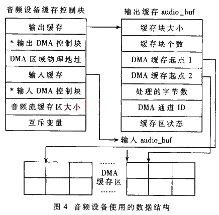
Using memory mapping (mmap) technology is another way to improve system performance. The memory space of the Linux system is divided into kernel space and user space; the driver works in kernel space and is responsible for transferring data between kernel space and user space. Audio applications generally involve large data volumes and high-quality requirements, and the driver can also use memory mapping to further improve CPU utilization. Memory mapping remaps the kernel space memory allocated for the DMA buffer to user space, allowing users to avoid using copy_to_user and copy_from_user to copy data between kernel space and user space. In Figure 4, the buffer state and buffer starting point fields are also used for memory mapping services. Due to the complexity of the DMA buffer structure, each buffer block needs to be mapped separately during implementation. 2.5 Device-Independent Operations Device-independent operations correspond to the various routines pointed to by file_operations, allowing users to access devices in a file-like manner. The primary interfaces provided for user programs for device operations are opening and reading/writing to the device, corresponding to the open, read, and write routines in file_operations. The main tasks to be completed in the open routine include: • Initializing the audio device by setting the IIS registers and initializing the working parameters of the device (including speed, channel, sampling width); • Allocating a DMA channel for the device; • Calculating the size of the buffer segment based on the sampling parameters (the program can also specify the size of the buffer segment); Once the buffer and DMA are set up, read/write operations primarily involve buffer operations. Besides read/write operations, there are also pause and continue operations during audio playback. These two operations are implemented in the ioctl interface by manipulating the corresponding IIS bus controller (IISCON register). Moreover, it is important to note that the data obtained from a single sample must be processed in one go; otherwise, the data cannot be played back correctly.
**********************************************
How to Share to Moments
Click the button in the upper right corner  →
→  Share to Moments
How to Follow “Chuangxue Electronics Network”
1. Enter WeChat “Contacts” → Click the upper right corner “Add” → Search for the public account “Chuangxue Electronics Network”
2. Or search for WeChat ID “Chuangxue Electronics Network”
3. You can also scan the QR code to follow:

**********************************************
Friendly Reminder:
Chuangxue Electronics Network Service Account: Chuangxue Electronics
Chuangxue Electronics Network Subscription Account: Chuangxue Electronics Network
**********************************************
www.eeskill.com Learn more exciting content!