Click the card below to follow Arm Technology Academy
Each external interrupt has a corresponding priority register. The Cortex-M0 has a total of 8 NVIC-IPR registers, with each register managing 4 IRQ interrupts. Therefore, the M0 can support a maximum of 32 IRQ interrupt sources, plus 16 core interrupts, meaning that M0 can support a total of 48 interrupt sources.
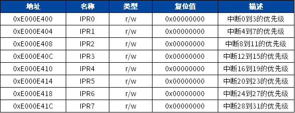
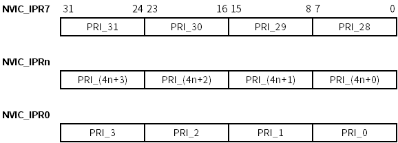
The Cortex-M0 adopts the Armv6-M architecture, and the priority register configuration bits are 8 bits, but only the highest 2 bits are valid. Many people who have used Cortex-M3 mistakenly believe that the Cortex-M0 also has 3 or 4 effective bits. ARM’s official documentation compares the differences between the two versions. Therefore, Cortex-M0 has 4 programmable priorities, plus 3 fixed priorities (Reset, NMI, HardFault), resulting in a total of 7 interrupt priorities for Cortex-M0.
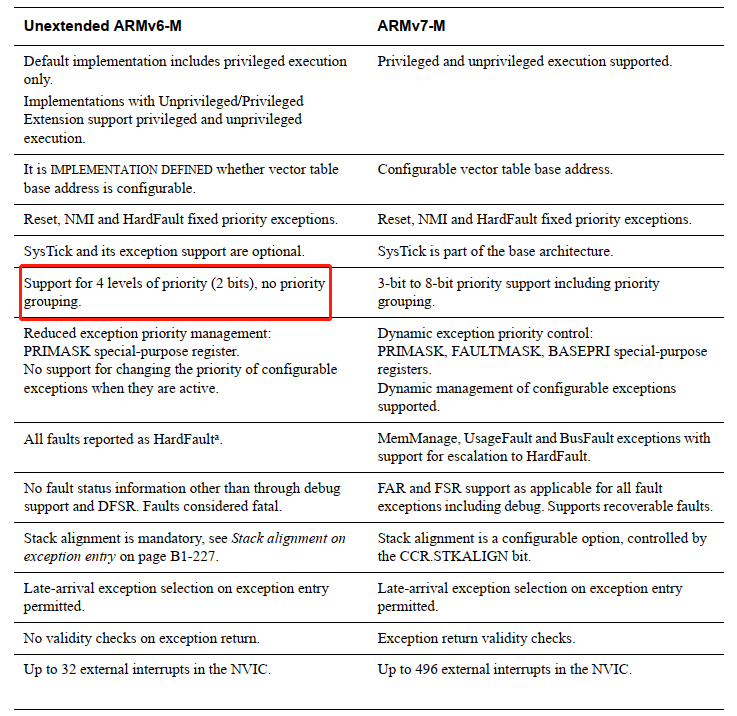
The interrupt priority registers of the Cortex-M0 core are aligned to the most significant bit (MSB) and only support word transfer. Each access involves 4 interrupt priority registers simultaneously. See the figure below:

Since Bit0 – Bit5 are not used, if no write operation is performed, the read value will be 0.
Due to the differences in interrupt priorities among different Cortex-M series, the number of priorities can be checked in the header files of the CMSIS library, specifically \\_\\_NVIC\\_PRIO\\_BITS.
The programming of the interrupt priority registers should be done before enabling the interrupts, which is usually completed at the start of the program. ARM’s official documentation advises against changing the interrupt priorities after enabling interrupts, as this can yield unpredictable results in the ARMv6-M system architecture and is not supported by the Cortex-M0 processor. The situation is different for Cortex-M3/M4 processors, which support dynamic switching of interrupt priorities. Another difference between the Cortex-M3 and Cortex-M0 processors is that the Cortex-M3 supports byte or half-word transfers when accessing interrupt priority registers, allowing for the setting of a single register at a time. If priority needs to be changed, the interrupt must be disabled in the program before resetting the interrupt priority register.
In the Cortex-M core, the lower the priority value of an interrupt, the higher its logical priority. For example, an interrupt with priority 2 can preempt an interrupt with priority 3, but not vice versa. In other words, interrupt priority 2 is higher than interrupt priority 3.
The Cortex-M0 processor supports interrupt nesting without any software intervention. If the MCU is already running an interrupt and a new higher-priority interrupt request arrives, the currently running interrupt will be paused, and the higher-priority interrupt will be executed. After the high-priority interrupt completes, it will return to the original lower-priority interrupt. If two interrupts of the same priority occur, the MCU will execute the interrupt that initiated the request first.
MM32F0130 series interrupt vector table:
typedef enum IRQn {

    NonMaskableInt_IRQn             = -14,                                  ///< 2 Non Maskable Interrupt
    HardFault_IRQn                  = -13,                                  ///< 3 Cortex-M0 Hard Fault Interrupt
    MemoryManagement_IRQn           = -12,                                  ///< 4 Cortex-M0 Memory Management Interrupt
    BusFault_IRQn                   = -11,                                  ///< 5 Cortex-M0 Bus Fault Interrupt
    UsageFault_IRQn                 = -10,                                  ///< 6 Cortex-M0 Usage Fault Interrupt
    SVC_IRQn                        = -5,                                   ///< 11 Cortex-M0 SV Call Interrupt
    DebugMonitor_IRQn               = -4,                                   ///< 12 Cortex-M0 Debug Monitor Interrupt
    PendSV_IRQn                     = -2,                                   ///< 14 Cortex-M0 Pend SV Interrupt
    SysTick_IRQn                    = -1,                                   ///< 15 Cortex-M0 System Tick Interrupt
    WWDG_IWDG_IRQn                  = 0,                                    ///< WatchDog Interrupt
    WWDG_IRQn                       = 0,                                    ///< Window WatchDog Interrupt
    PVD_IRQn                        = 1,                                    ///< PVD through EXTI Line detect Interrupt
    BKP_IRQn                        = 2,                                    ///< BKP through EXTI Line Interrupt
    RTC_IRQn                        = 2,                                    ///< RTC through EXTI Line Interrupt
    FLASH_IRQn                      = 3,                                    ///< FLASH Interrupt
    RCC_CRS_IRQn                    = 4,                                    ///< RCC & CRS Interrupt
    RCC_IRQn                        = 4,                                    ///< RCC Interrupt
    EXTI0_1_IRQn                    = 5,                                    ///< EXTI Line 0 and 1 Interrupts
    EXTI2_3_IRQn                    = 6,                                    ///< EXTI Line 2 and 3 Interrupts
    EXTI4_15_IRQn                   = 7,                                    ///< EXTI Line 4 to 15 Interrupts
    HWDIV_IRQn                      = 8,                                    ///< HWDIV Global Interrupt
    DMA1_Channel1_IRQn              = 9,                                    ///< DMA1 Channel 1 Interrupt
    DMA1_Channel2_3_IRQn            = 10,                                   ///< DMA1 Channel 2 and Channel 3 Interrupts
    DMA1_Channel4_5_IRQn            = 11,                                   ///< DMA1 Channel 4 and Channel 5 Interrupts
    ADC_COMP_IRQn                   = 12,                                   ///< ADC & COMP Interrupts
    COMP_IRQn                       = 12,                                   ///< COMP Interrupts
    ADC_IRQn                        = 12,                                   ///< ADC Interrupts
    ADC1_IRQn                       = 12,                                   ///< ADC Interrupts
    TIM1_BRK_UP_TRG_COM_IRQn        = 13,                                   ///< TIM1 Break, Update, Trigger and Commutation Interrupts
    TIM1_CC_IRQn                    = 14,                                   ///< TIM1 Capture Compare Interrupt
    TIM2_IRQn                       = 15,                                   ///< TIM2 Interrupt
    TIM3_IRQn                       = 16,                                   ///< TIM3 Interrupt
    TIM14_IRQn                      = 19,                                   ///< TIM14 Interrupt
    TIM16_IRQn                      = 21,                                   ///< TIM16 Interrupt
    TIM17_IRQn                      = 22,                                   ///< TIM17 Interrupt
    I2C1_IRQn                       = 23,                                   ///< I2C1 Interrupt
    SPI1_IRQn                       = 25,                                   ///< SPI1 Interrupt
    SPI2_IRQn                       = 26,                                   ///< SPI1 Interrupt
    UART1_IRQn                      = 27,                                   ///< UART1 Interrupt
    UART2_IRQn                      = 28,                                   ///< UART2 Interrupt
    CAN_IRQn                        = 30,                                   ///< CAN Interrupt
    USB_IRQn                        = 31,                                   ///< USB Interrupt
} IRQn_Type;
The process of setting interrupt priority: first read a word, then modify the corresponding byte, and finally write the entire word back.
1.1. C Code
void __NVIC_SetPriority()
{
    unsigned long temp;                              // Define a temporary variable
    temp = *(volatile unsigned long)(0xE000E400); // Read IPR0 value
    temp &= (0xFF00FFFF |(0xC0 << 16));            // Modify interrupt #2 priority to 0xC0
    *(volatile unsigned long)(0xE000E400) = temp; // Set IPR0
}
1.2. Assembly Code
Multiple interrupt priorities can be set at once in the program.
void __NVIC_SetPriority()
{
    LDR R0, =0xE000E100   ;  // Set the address of the enable interrupt register
    MOVS R1, #0x4         ;  // Interrupt #2
    STR R1, [R0]          ;  // Enable interrupt #2
    LDR R0, =0xE000E200   ;  // Set the address of the pending interrupt register
    MOVS R1, #0x4         ;  // Interrupt #2
    STR R1, [R0]          ;  // Pend interrupt #2
    LDR R0, =0xE000E280   ;  // Set the address of the clear pending interrupt register
    MOVS R1, #0x4         ;  // Interrupt #2
    STR R1, [R0]          ;  // Clear the pending state of interrupt #2
}
1.3. CMSIS Standard Device Driver Functions
// Set interrupt priority
__STATIC_INLINE void __NVIC_SetPriority(IRQn_Type IRQn, uint32_t priority)
{
    if ((int32_t)(IRQn) >= 0) {
        NVIC->IP[_IP_IDX(IRQn)]  = ((uint32_t)(NVIC->IP[_IP_IDX(IRQn)]  & ~(0xFFUL << _BIT_SHIFT(IRQn))) |
                                    (((priority << (8U - __NVIC_PRIO_BITS)) & (uint32_t)0xFFUL) << _BIT_SHIFT(IRQn)));
    }
    else {
        SCB->SHP[_SHP_IDX(IRQn)] = ((uint32_t)(SCB->SHP[_SHP_IDX(IRQn)] & ~(0xFFUL << _BIT_SHIFT(IRQn))) |
                                    (((priority << (8U - __NVIC_PRIO_BITS)) & (uint32_t)0xFFUL) << _BIT_SHIFT(IRQn)));
    }
}
Here, the parameter IRQn is the interrupt ID number, which can be negative or positive. When IRQn is negative, it sets the priority of system exceptions; when IRQn is greater than or equal to 0, it sets the priority of peripheral interrupts. The chip manufacturer will provide the interrupt vector table IRQn_Type, and the application layer only needs to call it; priority can be 0, 1, 2, or 3, and the function will automatically shift to the corresponding highest 2 bits.
Method 1:
void NVIC_SetPriority(TIM1_CC_IRQn, 3); // Set the priority of interrupt #14 to 0xC0
Method 2:
void NVIC_Config(void)
{    NVIC_InitTypeDef NVIC_InitStructure;

    NVIC_InitStructure.NVIC_IRQChannel = TIM1_CC_IRQn;
    NVIC_InitStructure.NVIC_IRQChannelPriority = 3;
    NVIC_InitStructure.NVIC_IRQChannelCmd = ENABLE;
    NVIC_Init(&&NVIC_InitStructure);
}
After setting the interrupt priority, the user can also read the currently set interrupt priority.
Recommended Reading
-
Cortex-M0 Interrupt Control and System Control (Part 1)
-
[Repeatedly Jumping] The Transformation Path from AC5 to AC6 (2) – “Two Slices of Bread with Cheese” Stack Model
-
Detailed Explanation of the Multi-core Startup Process of SOC
Follow Arm Technology Academy