Abstract: This paper uses TI’s C5000 series general-purpose DSP chip TMS320VC5509 as the core to design and implement the hardware platform of the audio decoding system, and studies the MP3 decoding algorithm and its implementation on this hardware platform. The entire system’s hardware platform includes the DSP core module, FLASH memory, audio CODEC, power supply, and other modules. This system communicates with the computer via a USB interface, downloads MP3 format data streams, and stores them in Flash. The DSP then reads the MP3 data stream from Flash, completes the decoding work, and plays it through the CODEC. At the same time, software programming for other decoding algorithms can be performed on the DSP, enabling audio encoding and decoding of multiple data stream formats, which provides strong software upgrade flexibility and also solves the low power consumption issue.
MPEG (Moving Picture Experts Group) is a working group of ISO/IEC that is responsible for establishing technical standards related to the compression and decompression of moving images, audio, and their combination. MPEG-1 Layer 3 (MP3) is the third layer of encoding and decoding algorithms in the MPEG-1 international audio standard (ISO/IEC 11172), which has advantages such as high compression ratio, good sound reproduction quality, and moderate algorithm complexity. Music produced in MP3 format using this standard has been widely used in digital audio storage and multimedia audio transmission over the Internet.
Currently, audio encoding and decoding solutions based on dedicated chips have low software upgrade flexibility, while solutions based on DSP are mostly based on the C54x platform. The technical methods to solve low power consumption are worthy of research.
Based on the above background, this paper proposes a research and implementation solution for an audio decoding system based on DSP. The main purpose of this project is to use TI’s C5000 series general-purpose DSP chip TMS320VC5509 as the core to complete the design of the system hardware platform and the implementation of the MP3 decoding algorithm on this hardware platform. The entire system’s hardware platform includes the DSP core module, FLASH memory, audio CODEC, power supply, and other modules. This system communicates with the computer via a USB interface, downloads MP3 format data streams, and stores them in Flash. The DSP then reads the MP3 data stream from Flash, completes the decoding work, and plays it through the CODEC. At the same time, software programming for other decoding algorithms can be performed on the DSP, enabling audio decoding of multiple data stream formats, which provides strong software upgrade flexibility and also solves the low power consumption issue.
1 Overall Design of the Hardware Platform
Currently, there are two solutions in the industry for MP3 decoding systems: one is to use dedicated chips that have the decoding algorithm hard-coded into integrated circuits. These chips integrate some external resources into the chip, simplifying the external circuits required for implementing the MP3 decoding system, making the entire system easier to develop. However, since the algorithm is hard-coded into the chip, it cannot be upgraded through software, and such chips are generally expensive. The other solution is to use general-purpose DSPs to implement the MP3 decoding system. This solution requires high software and hardware skills from designers but has good upgrade characteristics and allows easier improvement and optimization of the decoding algorithm for better sound playback quality, while also being low in power consumption like the first solution.
Considering the advantages and disadvantages, we chose the second solution, which is to implement the entire decoding system’s hardware platform based on general-purpose DSP chips. The block diagram of the hardware system is shown in Figure 1.
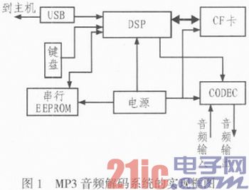
This block diagram roughly outlines the basic components of the decoding system. In the diagram, we used a 512 k serial EEPROM chip for the bootloader and a CF card to store MP3 music and decoding programs. The core processor uses TI’s TMS320VC5509 DSP chip, considering that its internal RAM capacity is 256 kB and our program size is 80 kB, so we did not expand the RAM in this design.
The entire hardware platform’s workflow is as follows: First, through the USB interface, MP3 music is copied from the PC to the large-capacity CF card. The DSP then reads the MP3 data from the CF card for decoding, restoring the PCM signal, and then transmits it to the audio CODEC chip through the DSP’s multi-channel buffered serial port (McBSP), ultimately playing the MP3 music.
1.1 Specific Implementation of the Hardware Platform
1.1.1 Introduction to the Core DSP Chip
The TMS320C55x series used in this solution is a new product launched by TI following the C5000 series C5x and C54x. It adopts an enhanced Harvard architecture, features a dedicated hardware multiplier, uses pipelined operations, and provides special DSP instructions that can quickly implement various digital signal processing algorithms. To facilitate practical applications, the C55X series DSPs have different hardware structures, such as on-chip memory and on-chip peripherals, which can be flexibly selected based on cost-effectiveness and different application scenarios. Due to its highly parallel hardware structure and modular design, the C55X series DSPs have advantages such as low power consumption and high speed. They are mainly used in audio compression, wireless communication, and other fields.
Compared with other chips in the 5000 series, the TMS320VC5509 is favored by users in the industry due to its unique high performance, low power consumption, and low price.
1.1.2 Interface Design with the Computer
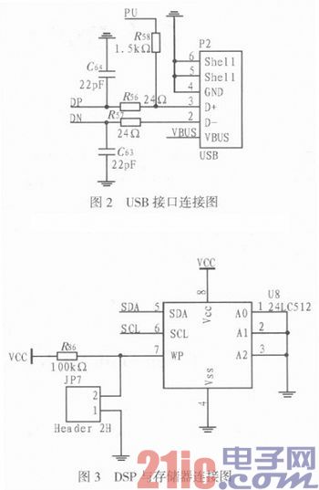
The interface design with the computer uses the currently popular USB interface to download data from the computer. The built-in USB interface of the 5509 fully complies with the USB 2.0 full-speed interface standard and can achieve high-speed parallel communication (12M bits/second) with any external microcontroller.
1.1.3 Memory Design
The CF card is used to store music and data files, connected to the DSP through the external memory interface (EMIF) and operates in True-IDE mode at a voltage of 3.3 V. We can choose any capacity CF card according to the system needs. A 64 kB EEPROM 24LC512 from Microchip Technology is used to store the boot program, which is loaded into memory for execution each time the power is turned on.
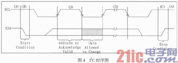
The interface between the 24LC512 and the DSP uses I2C bus communication. The I2C (Inter-Integrated Circuit) bus is a two-wire serial bus developed by PHILIPS for connecting microcontrollers and their peripherals. The I2C bus consists of a data line (SDA) and a clock line (SCL), which can send and receive data. It allows bidirectional transmission between the CPU and controlled ICs, and between ICs, with a maximum transmission rate of 100 kbps. Various controlled circuits are connected in parallel on this bus, but like a telephone, each circuit must dial its unique number to work, so each circuit and module has a unique address. During the information transmission process, each module circuit connected to the I2C bus can act as both a master controller (or controlled device) and a transmitter (or receiver), depending on the function it needs to perform. The control signals sent by the CPU are divided into two parts: address code and control quantity. The address code is used for addressing, which connects the circuit that needs to be controlled and determines the type of control; the control quantity determines the category (such as volume) and the amount to adjust. Thus, although all control circuits are connected to the same bus, they are independent of each other. The timing diagram is shown in Figure 4.
1.1.4 Audio Decoding Interface Design
The audio CODEC chip used is TI’s TLV320AIC23. Its main function is to convert the PCM audio stream decoded by the DSP into an analog sound signal for playback through D/A conversion.
The TLV320AIC23 DSP Codec is a high-performance single-chip stereo codec launched by Texas Instruments in 2001. It supports selectable data conversion word lengths of 16/20/24/32 bits, and its operating voltage is compatible with the core and I/O voltage of the TMS320C55x DSP, allowing seamless connection to the C55x DSP serial port. It has low power consumption and compatible control interfaces of I2C and SPI bus that enable the AIC23 codec to be used with other microprocessors.
Its main features are as follows:
1) High-performance stereo codec: Supports sampling rates from 8 to 96 kHz, with 90 dB ADC and 100 dB DAC conversion signal-to-noise ratios, and core digital supply voltage of 1.42 to 3.6 V, as well as analog supply voltage of 2.7 to 3.6 V, all compatible with C55x DSP.
2) Programmable multiple serial data transmission standards: Supports I2C and SPI serial data transmission modes, both compatible with the McBSP port of C55x DSP.
3) Built-in amplified stereo input and output (adjustable gain), headphone amplifier module output (30 mW).
4) Low power management: 19 mW in recording and playback mode, less than 150 uW in standby mode, and less than 15 uW in stop mode.
The hardware interface circuit between the audio CODEC and DSP is shown in Figure 5.
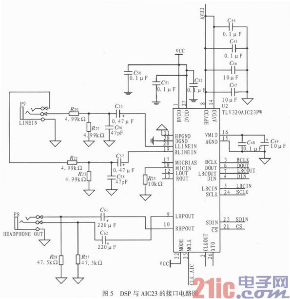
From the above figure, we can see that the interface of DSP VC5509 and AIC23 can be divided into two parts: the control interface part (McBSP1) and the audio data interface part (McBSP0). The McBSP1 port of the DSP completes the control function of AIC23, and this control port is configured as a commonly used SPI interface mode; while the McBSP0 port completes the audio data transmission function, and this data port is configured as DSP format.
The digital audio interface of AIC23 supports four data formats: Right-Justified, Left-Justified, I2S format, and DSP format. The timing of the SPI mode for the control interface and the timing of the DSP mode for the digital audio interface are shown in Figures 6 and 7, respectively.
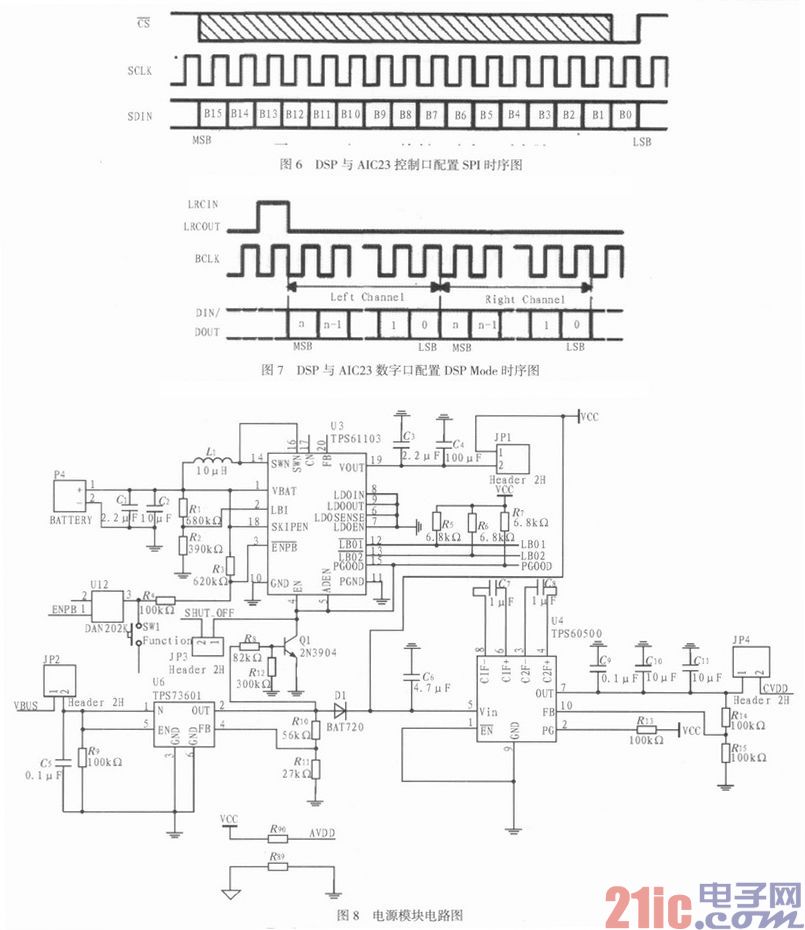
1.1.5 Power Module Design
In the power module, we selected three chips from TI, namely TPS61103, TPS60500, and TPS73601. The TPS61103 is used to convert the input battery voltage of 1 to 3 V to a fixed 3.3 V to supply power to the DSP’s I/O and other peripherals. The TPS60500 converts 3.3 V to the core voltage of 1.6 V required by the DSP. When the system is connected to the computer via the USB interface, it can be set up with appropriate jumpers without needing to connect a battery. The TPS73601 converts the 5V voltage provided by the USB interface to 3.3V.
2 Software Research and Algorithm Implementation
2.1 Implementation of the File System
By implementing the FAT32 file system, when this system is connected to a PC via USB, it will appear as an independent storage device in the Windows operating system, allowing music files to be copied to the CF card through copy and paste operations.
2.2 Implementation of the MP3 Decoding Algorithm
The software development platform for this solution is TI’s C5000 series integrated development environment Code Composer Studio 2.0. Considering the complexity and readability of the MP3 decoding software, the entire decoding software is written in C language for DSP. The C language for DSP has the same syntactical characteristics as standard ANSI C language, while also combining with DSP hardware, allowing direct control of DSP’s on-chip or peripheral resources. With the continuous development of digital signal processing technology, the compilation efficiency of the DSP C language compiler has also increased. The compiler efficiency for the 5000 series can reach 60% to 70%, and for the C6x series, it can reach up to 80%. Therefore, programming the DSP in C language is an inevitable trend.
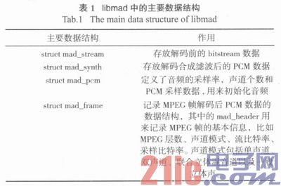
This solution designs the software based on LIBMAD. MAD (LIBMAD) is an open-source high-precision MPEG audio decoding library that supports MPEG-1 (Layer I, Layer II, and Layer III). LIBMAD provides 24-bit PCM output, which is purely fixed-point computation, making it very suitable for use on platforms without floating-point support. By using a series of APIs provided by LIBMAD, it is very simple to implement the MP3 data decoding work. In the mad.h file located in the source code directory of LIBMAD, most of the library’s data structures and APIs can be found.
Although the MP3 decoding algorithm is complex, the entire decoding process is divided into various modules, and each module is relatively independent. During the design process of the entire decoding software, sub-functions are used for each module, and the connections between each module are expressed as function parameter passing. The entire decoding software is controlled by a main function that schedules the orderly operation of each module.
The program flow of the decoding software is shown in Figure 9. From the figure, we can see that the input audio stream decoding first goes through frame synchronization, reading the synchronization header’s information to obtain parameters such as the sampling frequency and bit rate of the MP3 bitstream, and records the number of frames currently being decoded in the MP3 bitstream. Then, it obtains granule information, main information, and scale factors, and reads information corresponding to each channel in each granule based on the compression type of the MP3 bitstream obtained from the synchronization header.
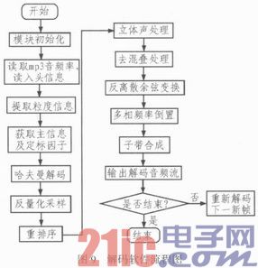
Next, two granules in a frame are decoded. First, the scale factors corresponding to each granule are obtained from the bitstream, and the data for each granule is subjected to Huffman decoding. This Huffman decoding process requires one of the 32 Huffman code tables to decode, which can be selected based on the information contained in the side information for each granule. The data after Huffman decoding is then subjected to inverse quantization sampling, where the data for each subband is inverse quantized using parameters obtained from the side information based on the type of window used. Following that is the reordering and stereo processing module, which processes the data according to the compression type used in the MP3 bitstream.
Once all channel data in a granule is processed, the decoded data for that granule can be output to the output buffer. When the data for the next granule is decoded and output, the entire frame of data is decoded. This frame of data can then be input to the D/A section for playback, and the output buffer is cleared to wait for the input of the next frame of decoded data. The decoding program continues until no more frame synchronization headers can be found in the bitstream, completing the decoding of this audio stream.
3 Conclusion
The MP3 decoding algorithm is relatively complex, and most portable MP3 players on the market use hardware decoders, specifically dedicated audio decoding chips. However, with the rapid development of digital signal processing technology, it has become possible to implement this decoding algorithm using general-purpose digital signal processors (DSPs), which outperform hardware decoding solutions in terms of cost-effectiveness, low power consumption, and software upgrade flexibility, becoming the development direction of the future MP3 market.
**********************************************
How to Share in Moments
Click the button in the upper right corner  →
→  Share to Moments
How to Follow “Changxue Electronics Network”
1. Go to WeChat “Contacts” → Click the upper right corner “Add” → Search for the public account “Changxue Electronics Network” in the search bar
2. Or search for the WeChat ID “Changxue Electronics Network”
3. You can also scan the QR code to follow:

**********************************************
Friendly Reminder:
Changxue Electronics Network Service Account: Changxue Electronics
Changxue Electronics Network Subscription Account: Changxue Electronics Network
**********************************************
www.eeskill.com Learn more exciting content!