Name: Design of an FPGA-Based Electronic Quiz Buzzer
Software: Quartus
Language: Verilog
Functionality:
FPGA-Based Electronic Quiz Buzzer
(1) The host has a control switch for the contestants to buzz in: contestants can only buzz in when the host presses this button; buzzing in before the start button is pressed is considered a violation. Contestants buzz in by pressing their assigned buttons. Each button can be connected to different input ports of the FPGA, allowing differentiation of key inputs from different contestants.
(2) When a button is pressed, the input signal may fluctuate multiple times due to mechanical bounce. This “bounce” can cause the FPGA to mistakenly interpret the key as being pressed multiple times. Therefore, a debouncing algorithm is used to filter out brief noise signals through sampling and timers. The buzzer has a timed buzzing function, with a buzz time set to 20 seconds. The FPGA implements the buzz time limit; if no one buzzes in within the specified time, it automatically locks out, and when the host presses the “start” button, the digital tube begins a countdown until it reaches zero. If no one buzzes in, that round is skipped, and the device automatically displays a score of 0 and starts the next round.
(3) When the FPGA detects that a button has been pressed through parallel processing logic, it starts a timer. This process can indicate which button was triggered first, thus determining the priority of the buzz. This can be achieved by setting up a state machine to track the pressed state of each button and calculate the time pressed. Once the order is determined, the system can generate corresponding signals for subsequent processing.
(4) When a button is successfully confirmed as pressed, the FPGA drives the LED display module to show the contestant’s number. Once a contestant successfully buzzes in, they can start answering the question. If the answer is correct, the host presses a button to add a point for that contestant, and then the next round of buzzing begins. After someone buzzes in, the system emits a sound through the sound module to notify all participants of the buzzing result.
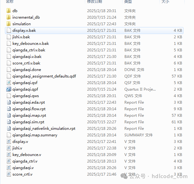
1. Project Files
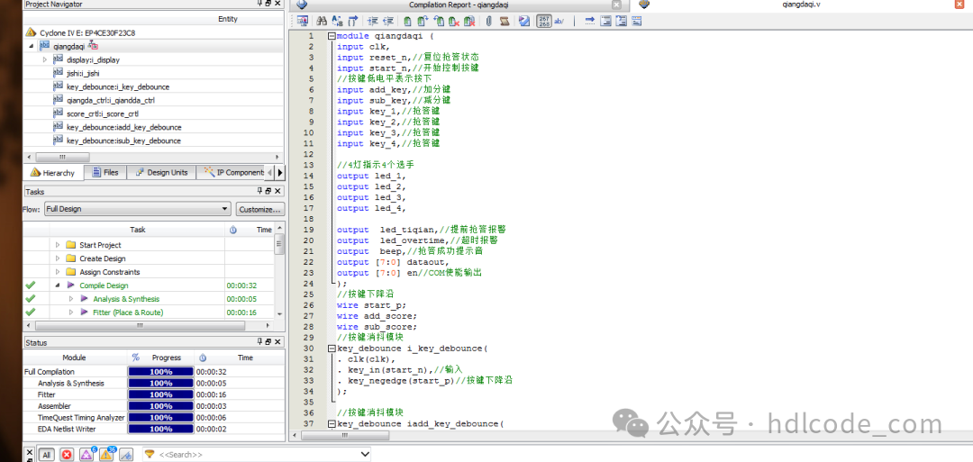
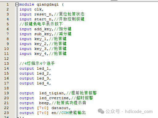
2. Program Files
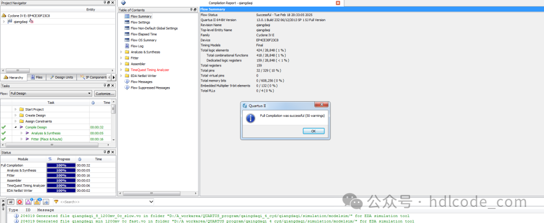
3. Program Compilation
4. RTL Diagram
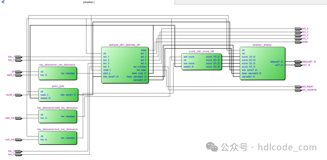
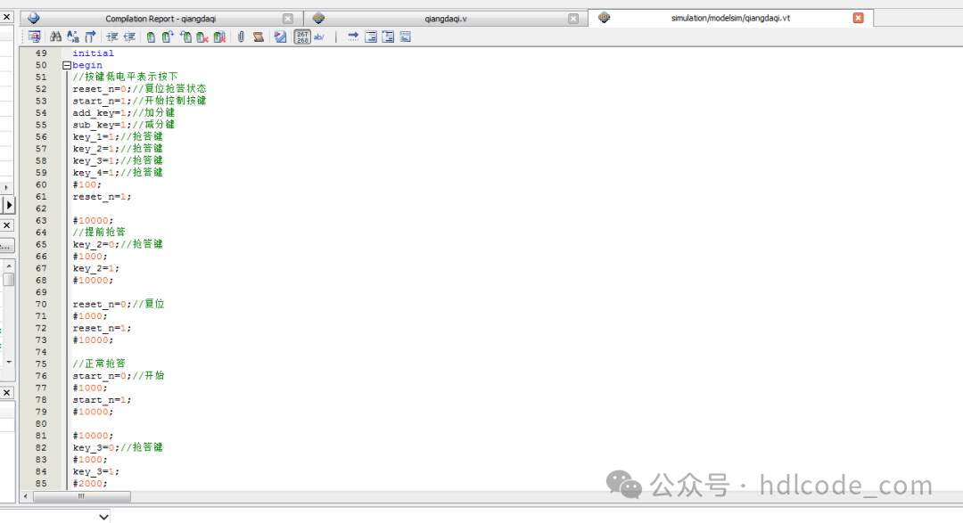
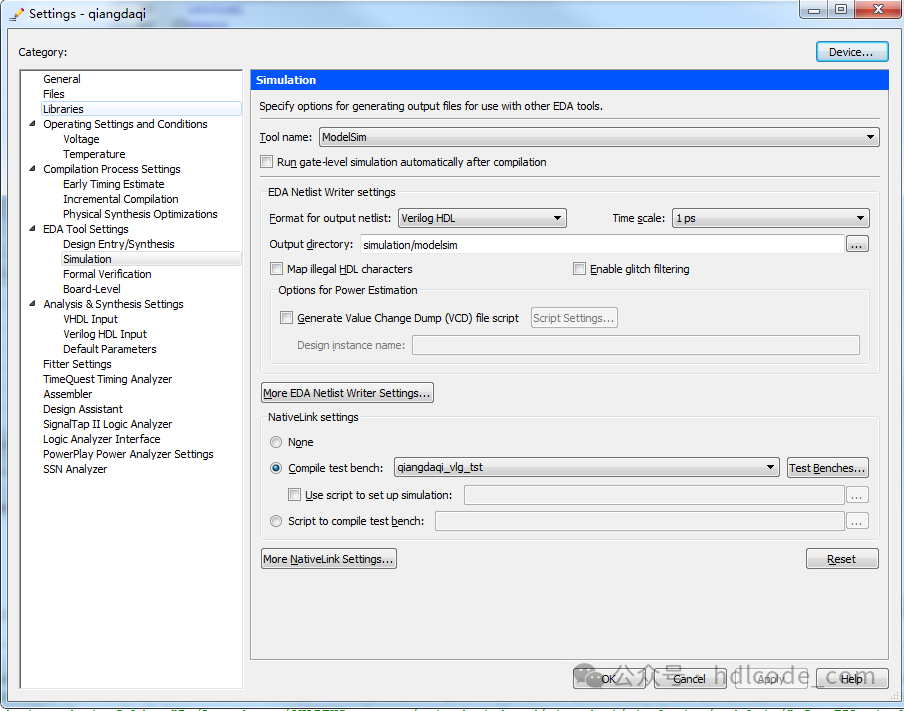
5. Testbench
6. Simulation Diagram
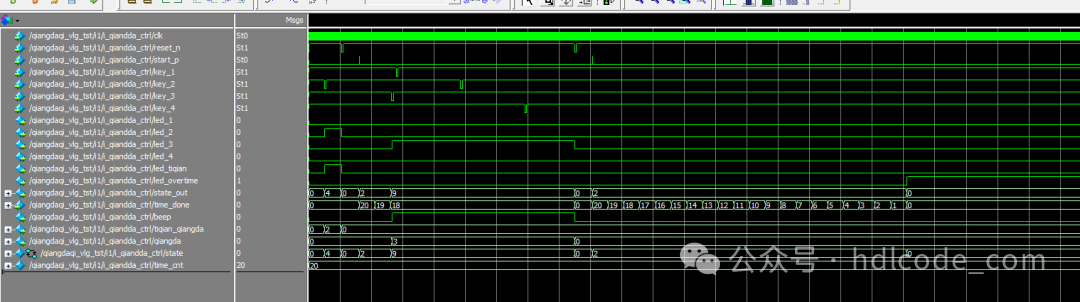
Overall Simulation Diagram
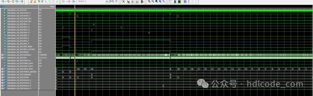
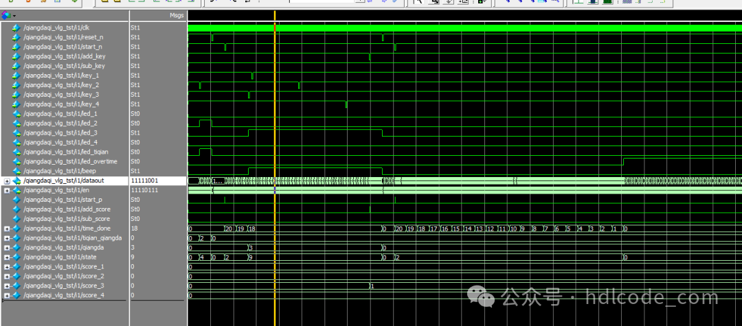
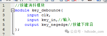
Key Debounce Module

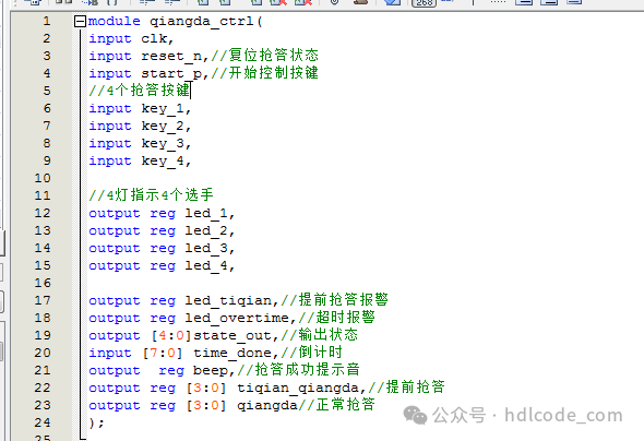
Control Module
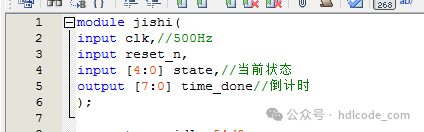
Timer Module

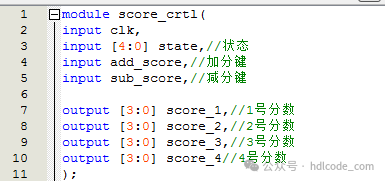
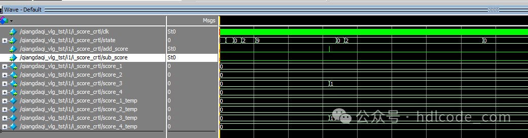
Score Control Module
Digital Tube Display Module
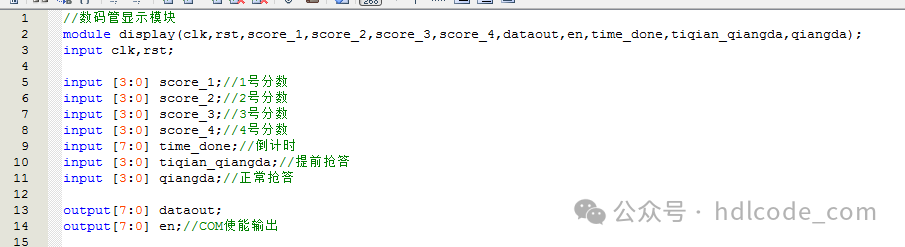
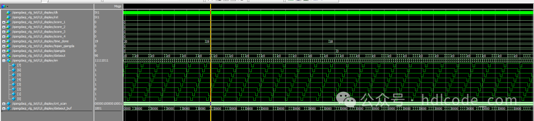
Partial code display:
// Key Debounce Module
module key_debounce(
input clk,
input key_in,// Input
output key_negedge// Key falling edge
);
// Inner signal
reg [1:0] key_in_r=0;
wire pp;
reg [19:0] cnt_base=0;
reg key_value_r=1;
reg key_value_rd=1;
// Internal signal
always@(posedge clk)
key_in_r <= {key_in_r[0],key_in};
// Detect if there is a change in input
assign pp = key_in_r[0]^key_in_r[1];
// Delay counter
always@(posedge clk)
if(pp==1’b1)
cnt_base <= 20’d0;
else
cnt_base <= cnt_base + 1;
// Output
always@(posedge clk)
//if(cnt_base==20’hfffff)// Reduce counter for simulation to f
if(cnt_base==20’h0000f)
key_value_r <= key_in_r[0];
Code file (paid download):