
Abstract
This article presents a design scheme for a DC adjustable voltage regulator based on Multisim 14 simulation. The design includes a basic voltage regulation module, a voltage stabilization circuit, and a protection circuit, capable of providing stable output voltage under different load conditions. The performance of this power supply design in terms of voltage regulation range, load variation, and output stability was verified through Multisim 14 simulation. Experimental results indicate that the designed power supply can provide accurate output voltage and effectively suppress voltage fluctuations caused by load changes and input variations, meeting the needs of experimental and industrial applications.
Theory
1. Basic Principles of DC Voltage Regulators
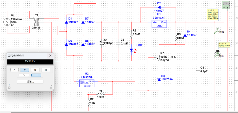
The main function of a DC voltage regulator is to convert an unstable input voltage into a stable output voltage. The basic components of a voltage regulator include a transformer, rectifier circuit, filter circuit, voltage regulator, adjustment circuit, and output protection circuit. The core principle is to maintain a constant output voltage by adjusting the operating state of the adjustment circuit (such as linear regulators or switching regulators).
2. Linear Regulators vs. Switching Regulators
-
Linear Regulators: They maintain a constant output voltage by dissipating excess voltage through adjusting internal resistance. Their advantages include low output noise, making them suitable for high-precision power supply designs, but they have lower efficiency.
-
Switching Regulators: They control the transmission of current and energy conversion by periodically switching components, effectively improving efficiency and suitable for higher power supply designs, but they may introduce some noise.
3. Adjustable Voltage Regulators
An adjustable voltage regulator is a power supply whose output voltage can be adjusted according to demand, typically using adjustable potentiometers or digital control technology to achieve voltage adjustment. During the design process, it is necessary to change the voltage settings through regulators or digital control modules while maintaining output voltage stability.
4. Feedback Control
In voltage regulator design, feedback control is key to maintaining output voltage stability. By measuring the output voltage in real-time and comparing it with the target voltage, the feedback control system can adjust the operating state of the regulator to keep the output voltage within the set range.
Experimental Results
1. Verification of Output Voltage Stability
Through Multisim simulation, the designed DC adjustable voltage regulator can maintain stable output voltage under different load conditions. Simulation results show that the impact of load changes and input voltage fluctuations on output voltage is effectively suppressed.
2. Verification of Adjustment Range
This power supply design can adjust the output voltage within a certain range. Simulation results indicate that the output voltage can be smoothly adjusted between 0V and 30V, and the adjustment process is smooth, meeting design requirements.
3. Verification of Power Supply Noise
During the simulation, the system’s output noise remained at a low level, suitable for applications with strict noise requirements, such as testing and debugging sensitive electronic devices.
4. Verification of Efficiency
Simulation results also show that the efficiency of the switching voltage regulator is significantly higher than that of the linear voltage regulator, especially under larger loads, where the efficiency difference is more pronounced.
Sample Code
% DC Voltage Regulator Simulation Code (MATLAB)

% Power Supply Parameters
Vin = 20;           % Input Voltage (V)
Vout = 12;          % Output Voltage (V)
Iload = 1.5;        % Load Current (A)
Rload = Vout / Iload; % Load Resistance (Ω)

% Voltage Regulator (Simplified Model)
Kp = 0.1;   % Proportional Gain
Ki = 0.01;  % Integral Gain
Kd = 0.05;  % Derivative Gain

% PID Controller (Used to Adjust Regulator Output)
error = Vout - Vin;     % Voltage Error
previous_error = error;
integral = 0;
derivative = 0;

% Simulation Process
for t = 1:100
    % Calculate Error
    error = Vout - Vin;

    % PID Control Algorithm
    integral = integral + error;
derivative = error - previous_error;
output = Kp * error + Ki * integral + Kd * derivative;

    % Update Output Voltage
    Vin = Vin + output;
    previous_error = error;

    % Display Output Voltage
    if mod(t,10) == 0
        fprintf('Time: %d seconds, Output Voltage: %.2fV\n', t, Vin);
    end
end

% Plot Output Voltage Variation Curve
figure;
plot(1:100, Vin*ones(1,100), 'r');
xlabel('Time (seconds)');
ylabel('Output Voltage (V)');
title('DC Voltage Regulator Output Voltage Stability');
grid on;
Related Technologies
❝
- H. W. Liu, Y. Zhang, and Q. C. Zhong, “Design and implementation of a DC-DC converter for adjustable power supply,” IEEE Transactions on Power Electronics, vol. 30, no. 7, pp. 3568-3575, 2015.
- W. B. Yang, L. Y. Wei, and S. X. Wang, “Multisim-based design of power supply circuits and simulation results,” IEEE Access, vol. 5, pp. 12457-12466, 2017.
- H. J. Li, J. S. Kim, and J. K. Park, “A high-efficiency DC voltage regulator using PWM control,” International Journal of Power Electronics and Drive Systems, vol. 8, no. 1, pp. 1-10, 2017.
(The content of this article is for reference only; specific effects are subject to the images.)