When conducting physical security assessments on IoT devices, one of the goals is to utilize debugging interfaces or accessible chips to study the device’s operation. Ideally, a complete file system is extracted from the device to find methods for gaining root access. This makes it easier to check which services are running, debug them if necessary, and ultimately gain control over the target device. Debugging interfaces often have protective measures that prevent access to their full functionality or set protections in the boot chain that prohibit any modifications. Fault injection is a method used to attempt to bypass such protections. In this article, we will delve into voltage fault injection to understand how it works.
Introduction
Fault injection is a technique used to assess device security by deliberately introducing faults or errors into hardware components to bypass security features such as debugging protections or password authentication. These injection operations should occur at specific moments and for a controlled duration to disrupt memory or skip instructions. Methods for achieving fault injection include:
-
Hardware devices
-
Software methods
-
Hybrid methods combining hardware and software
This type of attack has been widely used in sensitive areas such as payment cards or content protection and has become easier to implement in recent years.
Let’s consider the following scenario: password verification is implemented through an if statement that returns 0 or 1. In the first case, the user is denied access; when it returns 1, the user can log in. Here are some possible outcomes during fault injection:
-
Injecting a specific value of 1 to bypass authentication.
-
Generating random bytes (this is more likely to occur). Depending on the implementation, some protections may still be bypassed.
-
Skipping instructions, such as the if statement itself.
Some registers may be corrupted, and the device may operate in a non-standard state. In the past, fault injection attacks have been used to break security measures, such as the reset fault attack on Xbox360, flash memory reading on STM32, secure boot bypass on MediaTek MT8163V3, or the recent successful fault injection attack on DJI drones.
Clock Fault Injection
Clock fault injection is an attack method targeting devices equipped with external clocks. By injecting clock fault pulses between normal clock pulse cycles at extremely precise moments, it is possible to remove or insert an edge between two legitimate clock edges in the raw clock signal used by the arithmetic logic unit (ALU). When this occurs, unexpected behavior may be triggered, such as the processor skipping an instruction, which may be the instruction responsible for security checks.
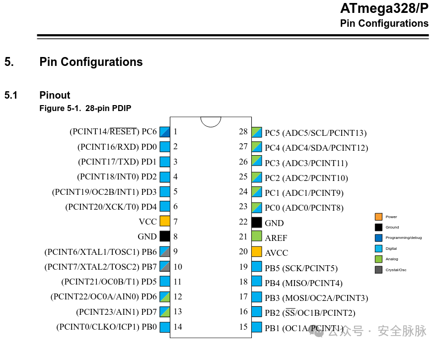
The fault injection course in the ChipWhisperer codebase provides a very clear example of such an attack on the Atmel AVRM ATMega 328P:
The system does not load and execute each instruction from FLASH but uses pipelining to speed up execution. This means one instruction is being decoded while the next instruction is being fetched, as shown in the figure below:
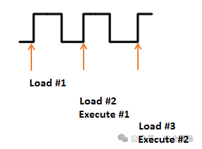
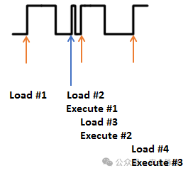
However, if the clock is modified, it is possible that the system does not have enough time to actually execute the instruction. Consider the following case, where “Execute #1″ is actually skipped. Before the system executes that instruction, another clock edge arrives, causing the microcontroller to start executing the next instruction.
 However, if your target device uses an internal clock signal, this method is generally not applicable.
Optical Fault Injection
The field of optical fault injection actually encompasses a variety of different techniques, from expensive equipment using X-rays to locate individual bits on flash memory cells to inexpensive methods using camera flashes to induce random faults to recover AES keys.
In hardware security assessments, the primary method used for security evaluation is laser fault injection (LFI). Pulsed lasers are used to physically manipulate and distort data, thereby inducing faults in running devices.
The main goal is to find the areas on the chip with the highest success rate for fault injection. When conducting such attacks, it is necessary to consider the X, Y, and Z coordinates to determine the optimal injection spatial position.
The standard equipment for this technique includes:
-
Control devices
-
Electric platforms
-
Laser sources
-
Objective lenses
However, this technique also has some side effects, such as the high cost of assembling the equipment and the need to remove the chip from the circuit board, which may damage the device. This is because fault injection is performed from the back of the chip, although new techniques have been developed to perform injection from the front.
Overall, optical fault injection technology offers high precision and repeatability but at a high cost.
Electromagnetic Fault Injection
Electromagnetic (EM) radiation affects both analog and digital modules, although their physical characteristics differ. To alter digital modules (which are clock-driven), brief electromagnetic pulses can be used to inject faults during specific clock cycles, which requires a high-voltage pulse generator and coils with ferrite cores (injection probes). This injection method strikes a good balance between cost and precision.
Unlike laser fault injection, electromagnetic fault injection does not require the chip to be desoldered from the circuit board and only requires finding suitable spatial positions in two dimensions. Additionally, unlike clock or voltage fault injection, electromagnetic fault injection does not require soldering or connecting wires to the chip.
The following image shows a PicoEMP device attacking a Raspberry Pi:
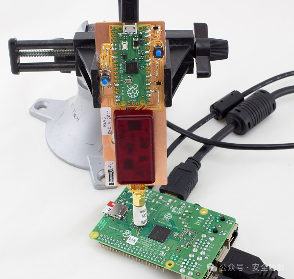
Electromagnetic fault injection is a practical technique for attackers. It offers good precision, with costs slightly higher than voltage or clock fault injection but far lower than laser fault injection. Moreover, this technique does not require desoldering or other invasive methods, thus maintaining the integrity of the system-on-chip (SoC). For such attacks, a method is to run an infinite loop while scanning the CPU surface with a grid. First, test one point multiple times, then move the probe to another point (usually about 1 millimeter apart), and so on, to complete the scanning of the entire SoC. Additionally, different sizes of probes can be used.
An application example of electromagnetic fault injection technology is Riscure’s related work, which interferes with the ESP32 CPU through fault injection to bypass secure boot hash verification during startup.
Voltage Fault Injection
The goal of voltage fault injection is to precisely control the power supply to the microcontroller, with control times kept sufficiently short. If the control time is too long, it will cause the chip to reset; however, if controlled correctly, it can put it into an undefined state, leading to unpredictable behavior. This means finding the appropriate fault pulse width and the right triggering timing is essential.
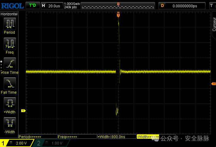 This is a screenshot of the oscilloscope during voltage fault injection. We can see that the voltage is first pulled down to near ground potential (GND), held for a while, and then quickly rises to nearly 14 volts before returning to its original state. By controlling the amplitude of the voltage change and its duration, it can lead to abnormal behavior in instructions, such as executing additional jump operations or altering an integer value.
One major issue faced by this method is the presence of components designed to maintain voltage stability, such as decoupling capacitors, which may interfere with the effects of fault injection. Therefore, it may be necessary to desolder these capacitors. Additionally, soldering the injection device as close to the target device as possible also helps improve the effectiveness of fault injection.
Creating a Simple Glitch
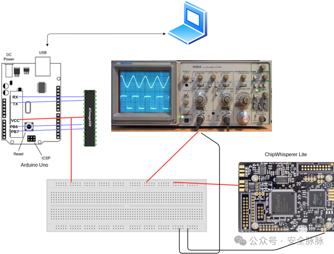
To detail the voltage fault injection on different targets, we used the ChipWhisperer Lite.
The short circuit is achieved through a MOSFET, which is a type of transistor whose main function is to control conductivity, i.e., to control the extent to which current flows between its source and drain based on the voltage applied to its gate. It can be modeled as a simple voltage-controlled switch. Here, we parallel it on the power rail to briefly short VCC to ground.
First, we perform a simple fault injection without any restrictions. For this, we used an Arduino Uno development board and placed the system-on-chip (SoC) on a breadboard. This allows us to conveniently control the ground of the microcontroller without interference from any decoupling capacitors. In other cases, to ensure our fault injection is as effective as possible, we may need to remove the decoupling capacitors connected to Vcore and reset lines. This can be done with a standard soldering iron and some patience.
The pins that need to be reconnected include at least PIN 2, 3 (RX / TX), 7 (VCC), 9, and 10 (Clock). These pins are responsible for basic power supply and operation as well as serial communication with the microcontroller. If code needs to be uploaded to the Arduino, Pin 1 (Reset) also needs to be connected. Use the oscilloscope to check if the fault occurs, with the probe connected to Pin 7. Below is a simple schematic to better understand these connections:
The code uploaded to the Uno board using the Arduino SDK is a fairly simple C++ script.
void setup() { Serial.begin(115200);}void loop() { int ctr = 0; for(int i=0; i<2; i++){ for(int j=0; j<2; j++){ delay(100); Serial.print("i: "); Serial.print(i); Serial.print(" j:"); Serial.print(j); Serial.print(" ctr:"); Serial.println(ctr); ctr++; } }}This is just a double for loop with a counter that increments from 0 to 3. The values of variables i and j increment from 0 to 1. Below is the Python script used for fault injection:
import chipwhisperer as cw cw.set_all_log_levels(cw.logging.CRITICAL) SCOPETYPE = 'OPENADC' PLATFORM = 'CWLITEXMEGA' scope = cw.scope() # We adjust the clock to fit with the ATMega 328p frequency scope.clock.clkgen_freq = 8E6 # Set clock to internal chipwhisperer clock scope.glitch.clk_src = "clkgen" #"enable_only" - insert a glitch for an entire clock cycle based on the clock of the CW (here at 8MHz so 0.125 micro seconds) scope.glitch.output = "enable_only" # Enable Low power and High power transistors. scope.io.glitch_lp = True scope.io.glitch_hp = True # LP provides a faster response, so sharper glitches. HP can provide better results for targets that have strong power supplies or decoupling capacitors that cannot be removed. scope.io.vglitch_reset() # it simply sets scope.io.glitch_hp/lp to False, waits delay seconds, then returns to their original settings. In short, reset the glitching module. # How many times the glitch is repeated scope.glitch.repeat = 1 # Send the glitch scope.glitch.manual_trigger() scope.dis()A fault signal was sent that lasted for an entire clock cycle, and the clock frequency was adjusted to match that of the ATMega 328p. The “repeat” parameter is used to control how many times the fault is repeated. Initially, we set this parameter value very low, then gradually increased it (we used increments of 50 repetitions each time, but to reduce the risk of damaging the device, smaller increment values can also be used) to observe the behavior of the Arduino under different settings.

The microcontroller had a high number of repetitions.
On the oscilloscope, we can see that the fault signal was sent:
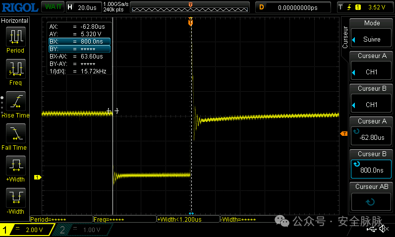
We tried placing cursors at the start and end points of the fault signal and set the clock frequency to 8MHz, so one clock cycle is 1/(8×10⁶)=1.25×10⁻⁷ seconds. The fault signal was repeated 500 times, so 1.25×10⁻⁷×500=0.0000625 seconds=62.5 microseconds. The measurement result showed 63.6 microseconds, so considering measurement error, everything is working fine.
As you can see, due to the fault signal being too strong, the Arduino Uno rebooted. In fault injection, the boundary between normal behavior and device reboot is very subtle, and some unusual things happen within this range. After some attempts, we found that when the fault signal was repeated 380 times, the device began to reboot. Therefore, we increased the repetition count of the fault signal from 1 to 380 and checked the behavior of the Arduino:
for i in range(380): scope.io.vglitch_reset(0.5) scope.glitch.repeat = i scope.glitch.manual_trigger()We recorded the minicom session and started the script. Next, we analyze its content:
i: 0 j:0 ctr:0i: 0 j:1 ctr:1i: 1 j:0 ctr:2i: 1 j:1 ctr:3i: 0 j:0 ctr:0i: 0 j:1 ctr:1i: 1 j:0 ctr:2i: 1 j:1 ctr:3i: 0 j:0 ctr:0i: 0 j:1 ctr:1i: 0 j:0 ctr:0i: 0 j:1 ctr:1i: 0 j:0 ctr:0i: 0 j:1 ctr:1i: 0 j:0 ctr:0i: 0 j:1 ctr:1As you can see, we successfully skipped some instructions. Initially, the counter jumped from 0 to 3, then to 2, and finally did not exceed 1. From the oscilloscope, it can be seen that during the execution of the script, the number of repetitions of the fault signal increased:

The oscilloscope shows a large fault signal.
If we want to modify certain values, it is clear that the fault signal here is too strong, as we skipped some loop iterations. We modified the script to send narrower fault signals and reduce the number of repetitions.
import chipwhisperer as cw [...] scope.clock.clkgen_freq = 192E6 # Maximum frequency of the internal clock of the CW [...] # insert a glitch for a portion of a clock cycle scope.glitch.output = "glitch_only" [...] gc = cw.GlitchController(groups=["success", "reset", "normal"], parameters=["width", "repeat"]) gc.set_range("width", 0, 35) gc.set_range("repeat", 1, 35) # The steps could be reduced to be more precise gc.set_global_step(1) for glitch_setting in gc.glitch_values(): scope.glitch.width = glitch_setting[0] scope.glitch.repeat = glitch_setting[1] print(f"{scope.glitch.width} {scope.glitch.repeat}") scope.glitch.manual_trigger() scope.io.vglitch_reset() scope.dis()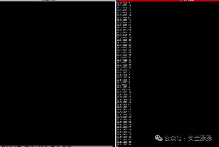
We successfully modified certain values during the execution of the script!
i: 0 j:-16777215 ctr:-16777215[...]i: -8023668 j:1 ctr:-805831672i: 1 j:0 ctr:-805831671i: 1 j:1 ctr:-805831670[...]Glitching a Logging Prompt
Our previous fault injection was not very precise, as we were sending fault signals at random times and waiting for abnormal behavior to occur. In the next example, we wrote a login prompt script on the Arduino Uno.
String PASSWORD = "passw";bool checkPass(String buffer) { for (int i = 0; i < PASSWORD.length(); i++) { if (buffer[i] != PASSWORD[i]) { return false; } } return true;}void setup() { Serial.begin(115200); Serial.println("Password:");}void loop() { if (Serial.available() > 0) { char pass[PASSWORD.length()]; Serial.readBytesUntil('\n', pass, PASSWORD.length()); bool correct = checkPass(pass); if (correct) { Serial.println("Logged in!"); Serial.flush(); exit(0); } else { Serial.println("Incorrect password."); Serial.println("Password:"); } }}We also enhanced the attack script to detect whether the Uno needs to be reset after fault injection.
import chipwhisperer as cw import time import serial import os cw.set_all_log_levels(cw.logging.CRITICAL) SCOPETYPE = 'OPENADC' PLATFORM = 'CWLITEXMEGA' scope = cw.scope() scope.clock.clkgen_freq = 192E6 scope.glitch.clk_src = "clkgen" scope.glitch.output = "glitch_only" scope.io.glitch_lp = True scope.io.glitch_hp = True gc = cw.GlitchController(groups=["success", "reset", "normal"], parameters=["width", "repeat"]) gc.set_global_step(0.4) gc.set_range("width", 1, 45) gc.set_range("repeat", 1, 50) gc.set_step("repeat", 1) for glitch_setting in gc.glitch_values(): # Try to connect to the Arduino Uno using the serial connection: try: with serial.Serial("/dev/ttyACM1", 115200, timeout=1) as ser: scope.glitch.width = glitch_setting[0] scope.glitch.repeat = glitch_setting[1] print(f"Width: {scope.glitch.width}, repeat: {scope.glitch.repeat}") # Send the glitch and a wrong password scope.glitch.manual_trigger() ser.write(b'tatat') scope.io.vglitch_reset() # If the serial connection breaks, use uhubctl to power off / power on the usb port on the USB hub where the Arduino Uno is plugged except Exception as e: os.system('/usr/sbin/uhubctl -S -p 2 -a cycle > /dev/null 2>&1') time.sleep(5) pass scope.dis()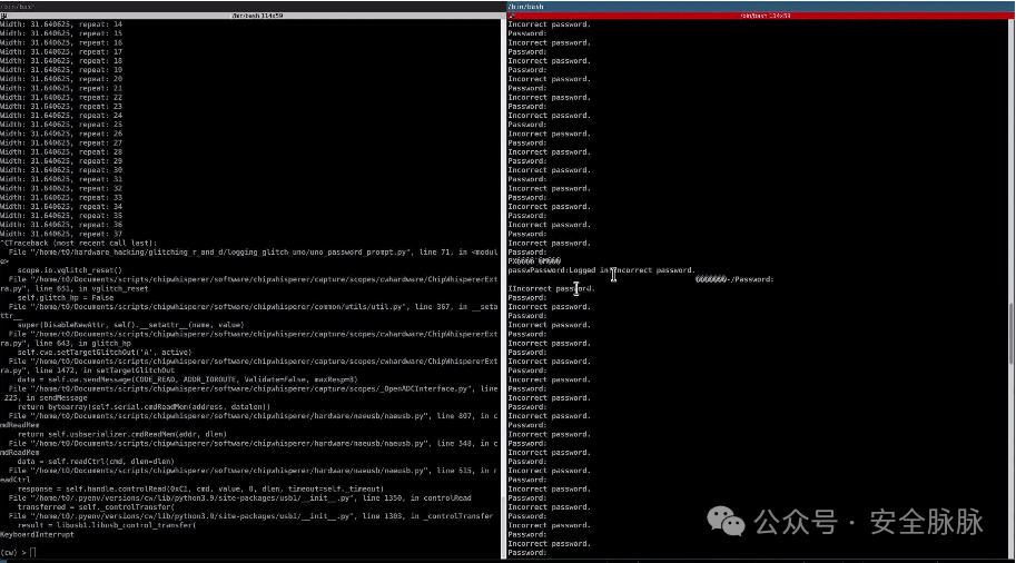 In this case, we not only bypassed the login prompt but also successfully recovered the password after about 30 minutes! This may be due to abnormal behavior occurring during the call to the println function.