“
Introduction: This article introduces CreativeLau’s post on Instructables Circuits[1], detailing the design and production of a handheld mini oscilloscope based on the STC microcontroller. It can measure voltage, signal waveforms, and can also generate common voltage waveforms for circuit testing.
Keywords:STC,DSO,Handheld Mini Oscilloscope
In Make Your Own Oscilloscope(Mini DSO) With STC MCU Easily, CreativeLau introduces his handheld mini oscilloscope based on an 8-bit microcontroller (STC8A8K64), which is both useful and fun for practice.

● Mini Oscilloscope Parameters: MCU Model:STC—MCU Waveform Time:100us-500ms Input Voltage Range:0-30V Drawing Mode:Vector or Point Set
01 Materials
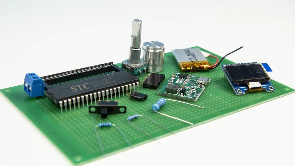
Components:
-
MCU: STC8A8K64S4A12×1 -
Display: SSD1306 OLED (5V, SPI 7PIN interface)×1 -
Resistors: 1W, 10k×1; 1/4W, 2k×2; 1/4W, 10k×1 -
Capacitors: 47uF×1; 0.01uF×1 -
Encoder: EC11×1 -
Toggle Switch: Quantity×1 -
Terminal Block: 2-Pin×1 -
IC Socket: 40-Pin×1 -
Single Row Socket: 7-Pin×1, 2-Pin×1 -
Lithium Battery: 3.7V Li-ion×1 -
Boost Module: 5V Boost Module×1 -
Downloader: USB-TTL downloader; -
Universal Breadboard: One piece
02 Circuit Making
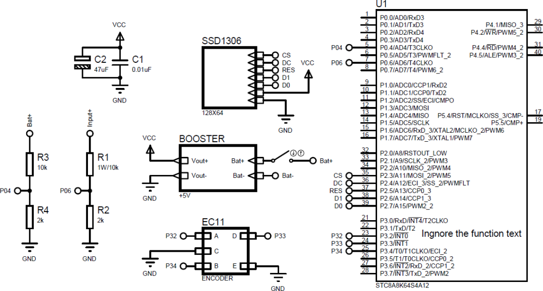
1. Circuit Design
1. Circuit Schematic
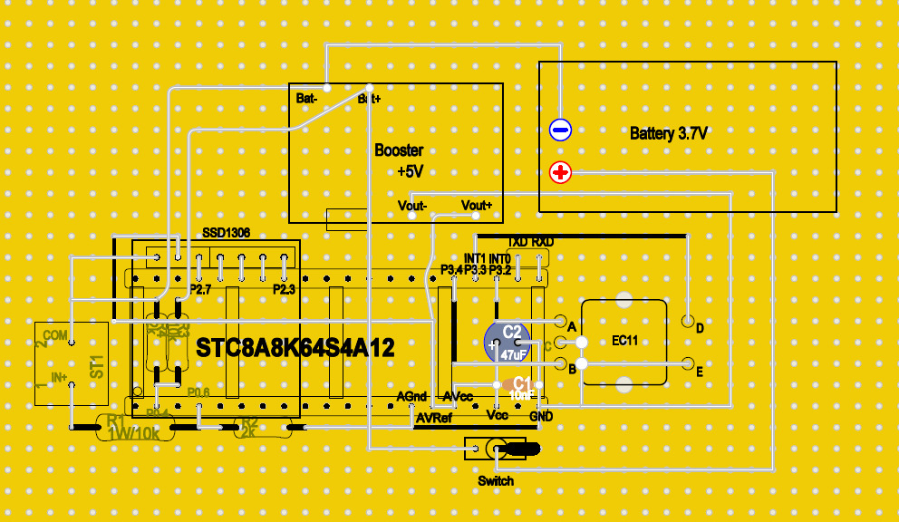
2. Circuit Component Layout Diagram
2. Soldering and Debugging
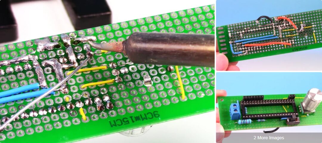
1. Circuit Soldering
Solder the entire circuit board on the breadboard.
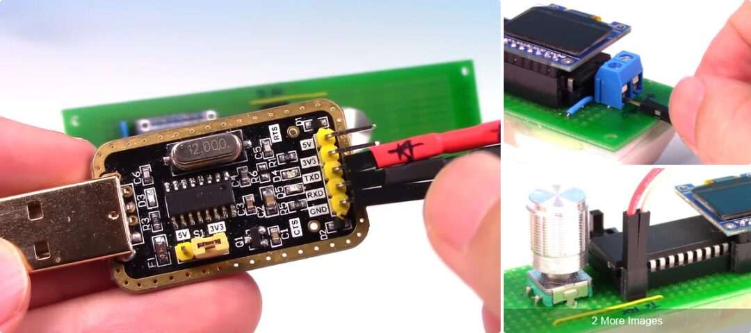
2. Downloading the Program
Download link for the STC microcontroller: http://www.stcmicro.com/rjxz.html. Use a USB-TTL serial connector to connect TXD, RXD, GND to the computer and the circuit to complete the download.
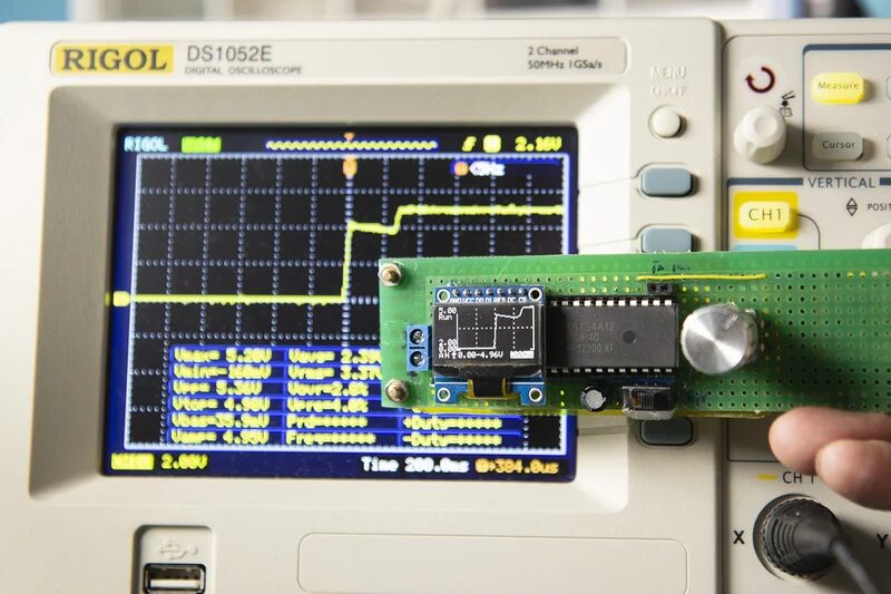
3. Power-On Testing
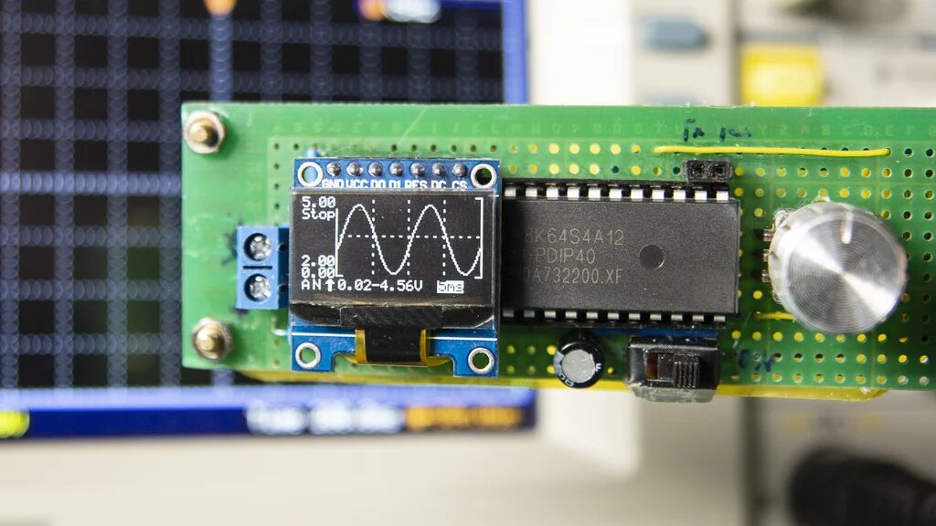
After connecting the lithium battery, the circuit can start working. It can be used directly to measure DC voltage or test voltage waveforms at test points in the circuit.
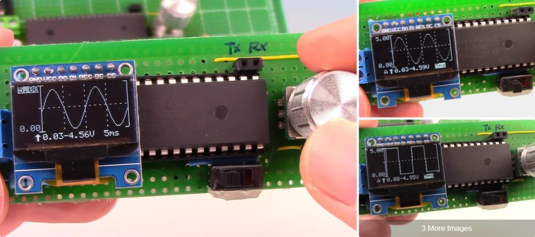
However, this version still has a problem: it cannot measure negative voltage. All negative voltages are displayed as 0V.
3. Other Functions
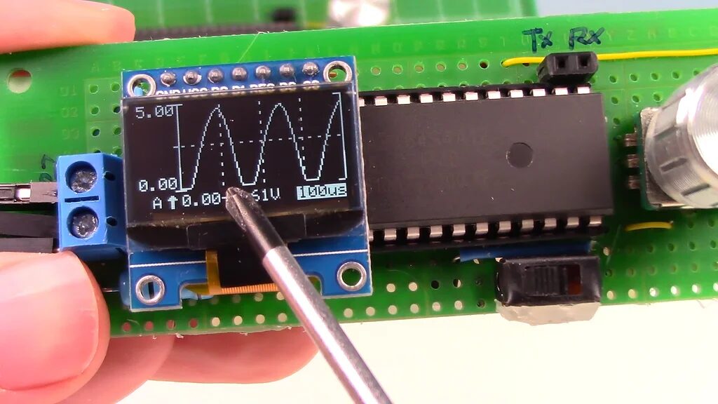
This small electronic tool can also be used as a signal generator, producing test signals for circuit testing.
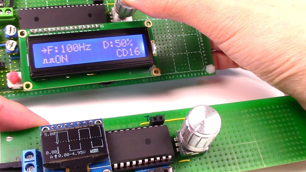
The following image shows the voltage waveforms produced by this small Mini DSO.
※ Conclusion ※
This article introduces CreativeLau’s post on Instructables Circuits[2], detailing the design and production of a handheld mini oscilloscope based on the STC microcontroller. It can measure voltage, signal waveforms, and can also generate common voltage waveforms for circuit testing.
References
Instructables Circuits: https://www.instructables.com/Make-Your-Own-OscilloscopeMini-DSO-With-STC-MCU-Ea/