
Click the blue text
Follow us
1. CRC Principle
1.1 Generating Polynomial
To understand CRC checks, one must first grasp the concept of the generating polynomial. The generating polynomial is simply a divisor agreed upon by the sender and receiver. Both parties use this same divisor to perform modulo-2 operations. If the results are the same, it indicates that the transmitted data is intact; if the results differ, it suggests that there may be an issue with the transmitted data. The goal is to ensure the reliability of data transmission.
The modulo-2 calculation mentioned above is essentially an XOR operation, where identical bits yield 0 and differing bits yield 1, disregarding carries and misalignments in binary addition and subtraction. For example: 10011011 + 11001010 = 01010001.
Common generating polynomials include:
CRC8 = X8 + X5 + X4 + 1
CRC16 = X16 + X15 + X5 + 1
CRC12 = X12 + X11 + X3 + X2 + 1
CRC32 = X32 + X26 + X23 + X22 + X16 + X12 + X11 + X10 + X8 + X7 + X5 + X4 + X2 + X1 + 1
Each generating polynomial corresponds to a specific code; for instance, the code corresponding to CRC8 is 100110001.
1.2 Communication Check Process
Assuming the polynomial of the message being processed is P(X), and the agreed polynomial between sender and receiver is G(X), the remainder polynomial R(X) is obtained by dividing P(X) by G(X). The remainder polynomial R(X) is then appended to the message polynomial P(X) to generate M(X). According to this calculation, the remainder of M(X) divided by G(X) should be 0. The sender then transmits M(X) to the receiver. If the receiver receives the message N(X) and divides it by the same divisor G(X), the remainder should also be zero. If the result is zero, it indicates that the sent and received sequences are consistent; otherwise, there is a transmission issue.
For example:
Assuming the information to be sent is 1011001, corresponding to the polynomial X6 + X4 + X3 = 1, if the agreed polynomial is G(X) = X4 + X3 + 1, which corresponds to the code 11001, then using the modulo-2 algorithm to find the remainder polynomial is as follows:
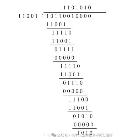
Before finding the remainder, the generating polynomial of the message to be sent is multiplied by the highest power of the agreed polynomial, which is then used as the dividend. The obtained remainder is 1010. Appending the remainder 1010 to the end of the message transforms the message into 10110011010.
Upon receiving this data, the receiver performs the division operation, and the remainder should be 0.
1.3 Generating Polynomials Used in CAN Bus
The basic principles of CRC checks have been discussed, and the difference in the CRC algorithm used in CAN communication lies in the generating polynomial, although the calculation method remains the same.
The following diagram illustrates the differences in generating polynomials used in various CAN implementations.
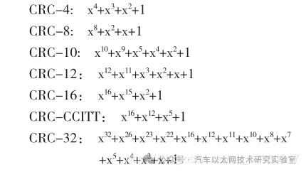
Traditional CAN uses the CRC15 algorithm, which can also be seen from the CAN data structure, where the length of the CRC segment is 15 bits. CAN FD has two types because the data length in CAN FD is variable; methods differ based on data length. For lengths below 16 bytes, CRC17 is used, while for lengths above 16 bytes, CRC21 is used.
2. Serial Implementation of CRC
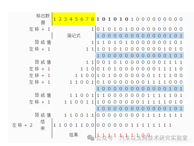
Based on the modulo-2 operation process in section 1.2, the steps for serial implementation of CRC16 are as follows:
(1) Predefine a 16-bit storage space for CRC and assign an initial value.
(2) Package the data to be sent into a Byte array (dividing the data into multiple Bytes for storage).
(3) Left shift the first data by 8 bits and XOR it with the current CRC value, placing the result in CRC.
(4) Check if the most significant bit (MSB) of the current CRC is 1. If it is, left shift by one, removing the MSB and appending 0 to the least significant bit (LSB), then XOR the new data with the simplified polynomial, storing the result in CRC. If the MSB is 0, only perform the left shift operation.
(5) Repeat steps 3-4 until all 8 data bits have been processed; at this point, the value in CRC is the desired checksum.
Assuming the data is 0xAA, the polynomial is 8005 (with the highest bit 1 omitted), the initial value is 0x00, and the output XOR value is 0x00. The following diagram demonstrates the correctness of the implementation process described above:
3.1 CRC Modulo-2 Operation and LFSR Implementation
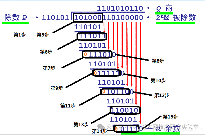
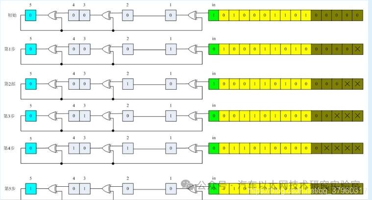
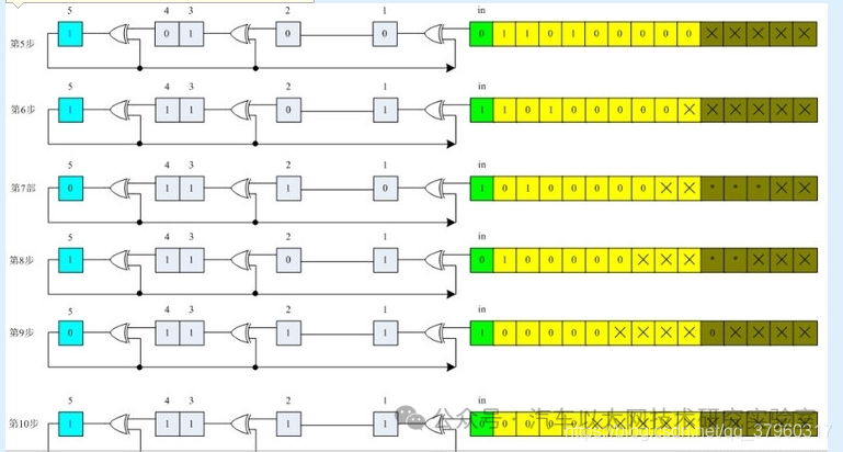
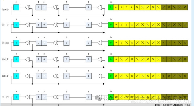
Assuming the information to be sent is M = 1010001101, the corresponding code for the generating polynomial is P = 110101, R = 5. After appending 5 zeros to M, perform modulo-2 division with P to obtain the remainder r(x) corresponding to the code: 01110. Therefore, the actual data to be sent is 101000110101110.
The corresponding polynomial is 110101, which is x5 + x4 + x2 + 1.
The modulo-2 division process is as follows:
The LFSR operation process is as follows:
3.2 CRC Code Implementation
If implemented using a sequential circuit, 8-bit data would need to be shifted 8 times, requiring 8 clock cycles, which is inefficient. To output results in a single clock cycle, combinational circuits must be used, trading space for time!
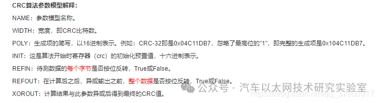
Using a CRC16 as an example, its implementation method is illustrated with parameters shown in the diagram.
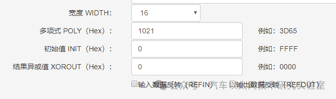
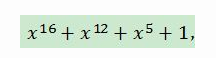
The polynomial for CRC16 is:
The LFSR circuit diagram is as follows. It is important to note that the data is shifted in from high to low. For 8-bit data, the processing order is Data[7] -> Data[0], which is why the first example used for(i=7; i>=0; i=i-1).

Two Verilog implementation methods yield identical results.
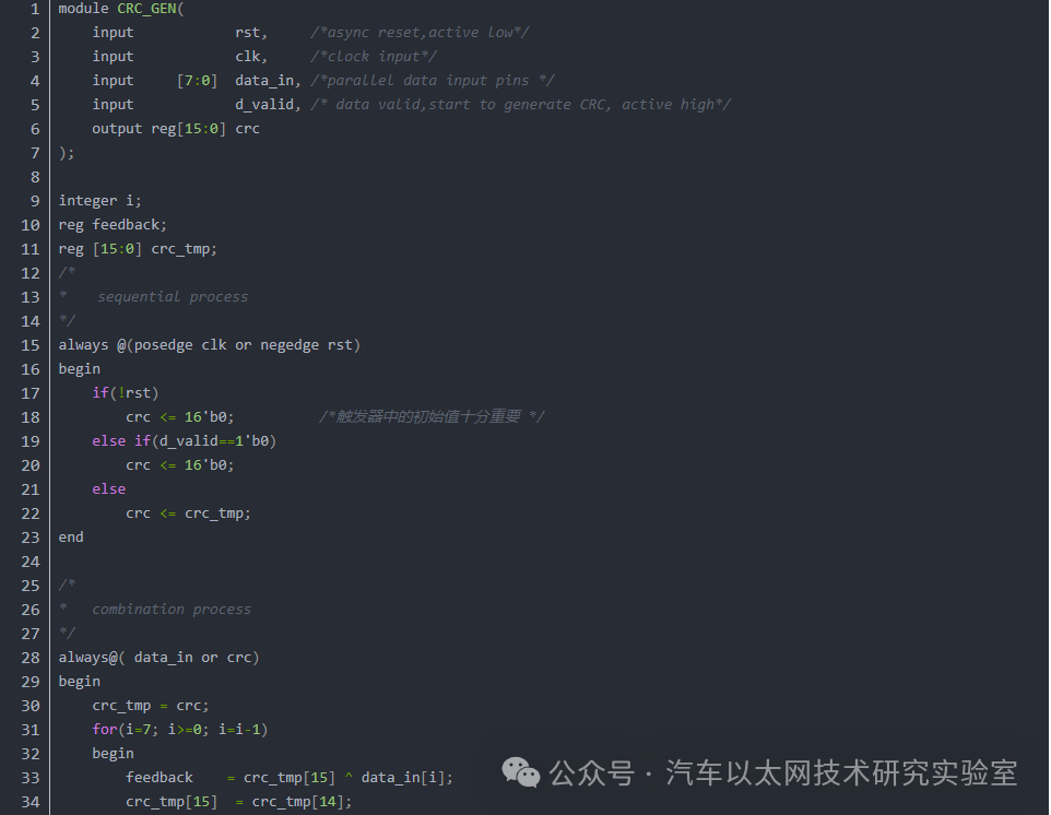
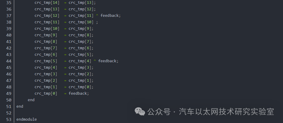
-
module CRC16_D8;
-
// polynomial: x^16 + x^15 + x^2 + 1
-
// data width: 8
-
// convention: the first serial bit is D[7]
-
function [15:0] nextCRC16_D8;
-
input [7:0] Data;
-
input [15:0] crc;
-
reg [7:0] d;
-
reg [15:0] c;
-
reg [15:0] newcrc;
-
begin
-
d = Data;
-
c = crc;
-
newcrc[0] = d[7] ^ d[6] ^ d[5] ^ d[4] ^ d[3] ^ d[2] ^ d[1] ^ d[0] ^ c[8] ^ c[9] ^ c[10] ^ c[11] ^ c[12] ^ c[13] ^ c[14] ^ c[15];
-
newcrc[1] = d[7] ^ d[6] ^ d[5] ^ d[4] ^ d[3] ^ d[2] ^ d[1] ^ c[9] ^ c[10] ^ c[11] ^ c[12] ^ c[13] ^ c[14] ^ c[15];
-
newcrc[2] = d[1] ^ d[0] ^ c[8] ^ c[9];
-
newcrc[3] = d[2] ^ d[1] ^ c[9] ^ c[10];
-
newcrc[4] = d[3] ^ d[2] ^ c[10] ^ c[11];
-
newcrc[5] = d[4] ^ d[3] ^ c[11] ^ c[12];
-
newcrc[6] = d[5] ^ d[4] ^ c[12] ^ c[13];
-
newcrc[7] = d[6] ^ d[5] ^ c[13] ^ c[14];
-
newcrc[8] = d[7] ^ d[6] ^ c[0] ^ c[14] ^ c[15];
-
newcrc[9] = d[7] ^ c[1] ^ c[15];
-
newcrc[10] = c[2];
-
newcrc[11] = c[3];
-
newcrc[12] = c[4];
-
newcrc[13] = c[5];
-
newcrc[14] = c[6];
-
newcrc[15] = d[7] ^ d[6] ^ d[5] ^ d[4] ^ d[3] ^ d[2] ^ d[1] ^ d[0] ^ c[7] ^ c[8] ^ c[9] ^ c[10] ^ c[11] ^ c[12] ^ c[13] ^ c[14] ^ c[15];
-
nextCRC16_D8 = newcrc;
-
end
-
endfunction
-
endmodule



*DisclaimerThis article is either original or forwarded by the author.If any party’s intellectual property rights are inadvertently infringed, please inform us for deletion.The above images and text are sourced from the internet. If there is any infringement, please contact us promptly, and we will delete it within 24 hours.The content of the article reflects the author’s personal views,and the Automotive Ethernet Technology Research Laboratory reproduces it solely to convey a different perspective, not representingthe Automotive Ethernet Technology Research Laboratory’s endorsement or support of this view. If there are any objections, please feel free to contact the Automotive Ethernet Technology Research Laboratory.
Original link:
https://blog.csdn.net/qq_37960317/article/details/110818193