Click the card below to follow Arm Technology Academy
The Cortex-M0 System Control Block (SCB) is one of the main modules of the core peripherals, providing system control and system execution information, including configuration, control, and reporting system exceptions.
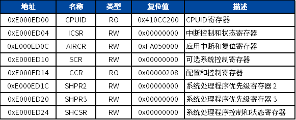
To improve software efficiency, CMSIS simplifies the representation of SCB registers. In CMSIS, the structure of the system control register is:
typedef struct
{    __IM  uint32_t CPUID; /*!< Offset: 0x000 (R/ )  CPUID Base Register */
    __IOM uint32_t ICSR;  /*!< Offset: 0x004 (R/W)  Interrupt Control and State Register */
    uint32_t RESERVED0;
    __IOM uint32_t AIRCR; /*!< Offset: 0x00C (R/W)  Application Interrupt and Reset Control Register */
    __IOM uint32_t SCR; /*!< Offset: 0x010 (R/W)  System Control Register */
    __IOM uint32_t CCR; /*!< Offset:0x014 (R/W) Configuration Control Register */
    uint32_t RESERVED1;
    __IOM uint32_t SHP[2U];/*!< Offset: 0x01C (R/W)  System Handlers Priority Registers. [0] is RESERVED */
    __IOM uint32_t SHCSR;  /*!< Offset: 0x024 (R/W)  System Handler Control and State Register */
} SCB_Type;
1. CPUID
The CPUID base address register contains information related to the processor model, version, etc. It is read-only and can be accessed through application software, debuggers, and programmers to obtain the processor type and version information.
Address: 0xE000ED00
Reset value: 0x410CC200
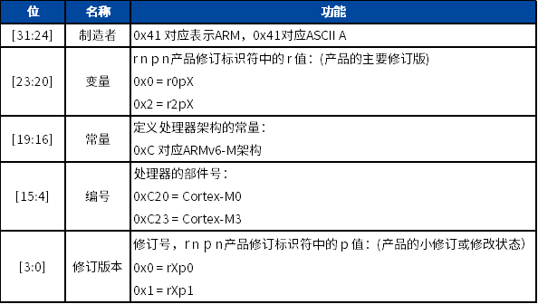
This CPUID is different from the 96-bit UID of the MCU we often mention. CPUID is the ID number of the processor, provided and implemented by Arm. Through CPUID, we can know the core model and version information. The 96-bit UID is the product ID of the MCU, belonging to MM32, provided by Shanghai Lingdong Microelectronics Co., Ltd., and implemented according to certain rules. The reference number provided by the 96-bit unique product identifier is unique for any series of microcontrollers and cannot be modified under any circumstances.
The MCU also has a DEV_ID code, which defines the device number and silicon version number of the MCU. It is part of DBG_MCU and is mapped to the external APB bus. This code can be accessed through the SW debug port (2 pins) or through user code.
DEV_ID Address: 0x40013400, supports only 32-bit access, read-only.
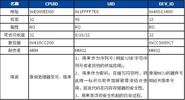
In the CMSIS driver library, you can directly use “SCB->CPUID” to get the processor ID. Reading the CPUID, UID, and DEV_ID of the MM32F0130 is as follows:
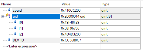
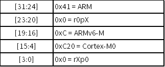
CPUID (0x410CC200) decodes processor information:
2. ICSR (Interrupt Control and State Register)
Provides:
-
Pending bit for NMI exception setting
-
Set and clear pending bits for PendSV and SysTick exceptions
Indicates:
-
Exception number of the currently processing exception
-
Whether there is a preempted active exception
-
Exception number of the highest priority pending exception
-
Whether there are any interrupts pending
Address: 0xE000ED04
Reset value: 0x0000 0000
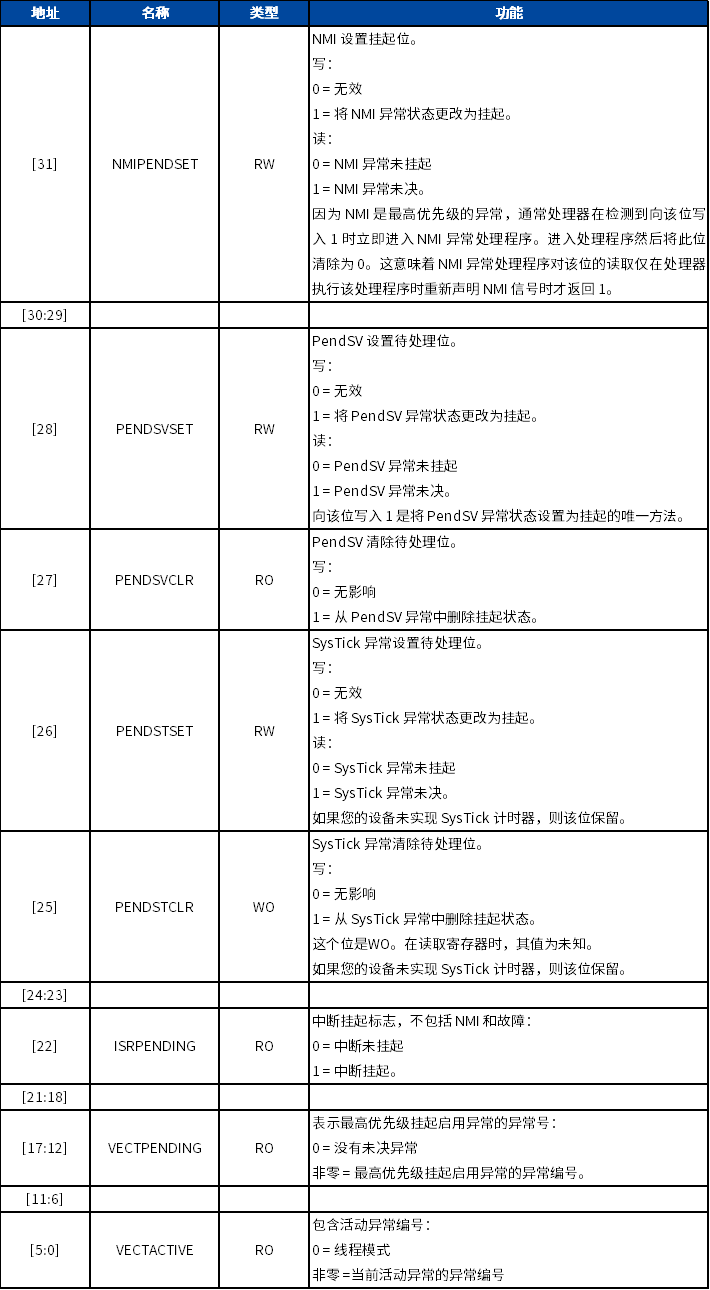
Some control bits in ICSR are for debugging purposes only. In most cases, applications will only use ICSR to control or check the system exception pending status.
PendSV (Pendable Service Call) exception is very important for OS operation, and its priority can be set by programming. PendSV interrupt can be triggered by setting bit 28 of the Interrupt Control and State Register (ICSR) to 1. Unlike SVC exceptions, it is imprecise, so its pending state can be set within higher priority exception handling and will be executed after high-priority handling is completed. Utilizing this feature, if PendSV is set to the lowest exception priority, PendSV exception handling can be executed after all other interrupt handling is completed, which is very useful for context switching and is a key aspect of various OS designs. In typical systems with embedded OS, processing time is divided into multiple time slices.
To start PendSV interrupt, write 1 to bit 28 of the Interrupt Control and State Register (ICSR). If the interrupt is enabled and there is a PendSV exception service function written, the core will respond to the PendSV exception and execute the PendSV exception service function, allowing task switching in the PendSV interrupt service function.
3. AIRCR (Application Interrupt and Reset Control Register)
AIRCR provides byte order status for data access and system reset control.
To write to this register, you must write the 0x05FA VECTKEY field, otherwise the processor will ignore the write.
Address: 0xE000ED0C
Reset value: 0xFA05 0000
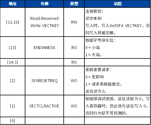
Any write operation to this register must write 0x05FA to AIRCR[30:16], otherwise the write operation will be invalid. If a half-word read is needed, write 0xFA05.
Soft reset function for system execution in the application:
__STATIC_INLINE void NVIC_SystemReset(void)
{    __DSB();  // Ensure all unfinished memory accesses including buffered writes are completed before reset
    SCB->AIRCR  = ((0x5FAUL << SCB_AIRCR_VECTKEY_Pos) |
                   SCB_AIRCR_SYSRESETREQ_Msk);
    __DSB();    // Ensure memory accesses are completed

    for(;;) /* wait until reset */
    {
        __NOP();
    }
}
4. SCR (System Control Register)
SCR controls the characteristics of entering and exiting low-power states.
Address: 0xE000ED10
Reset value: 0x0000 0000
Recommended Reading
-
Cortex-M0 Interrupt Control and System Control (Part 3)
-
Cortex-M0 Interrupt Control and System Control (Part 2)
-
Cortex-M0 Interrupt Control and System Control (Part 1)
Follow Arm Technology Academy