The CAN-FD bus protocol has a high effective data rate and is widely used in automotive internal buses. This paper introduces the design of a CAN-FD protocol controller driver based on the Cortex-M0 processor, detailing the development process of the CAN-FD driver. It achieves multi-node communication by communicating with other CAN-FD nodes and captures CAN-FD frames on the physical bus using a CAN-FD analyzer and a logic analyzer. Through actual CAN-FD communication projects, this paper completes the design process of the driver and provides reference value for the driver design of other CAN-FD devices.
Compared to the traditional CAN protocol, CAN-FD has a faster data transmission rate and more flexible and efficient data transmission. Unlike the CAN protocol’s transmission efficiency of 8 bytes per frame, CAN-FD can increase the transmitted data to a maximum of 64 bytes. At the same time, the transmission efficiency has also improved. CAN-FD can be installed on low-power chips like the Cortex-M0, effectively reducing power consumption.
The architecture designed in this paper centers around the Cortex-M0 as the core processor. The on-chip interconnect bus used by the Cortex-M0 processor is the AMBA bus, which includes the high-speed bus AHB and the low-speed bus APB. The CAN-FD protocol controller IP is one of the peripherals of the APB bus, along with others including TIMER, serial ports, watchdogs, and the dedicated message RAM for the CAN-FD protocol controller, as shown in Figure 1.In this system architecture, the Cortex-M0 is the main module of the AHB bus, responsible for initiating read and write operations. The AHB-APB bridge is the slave module of the AHB bus and the master module of the APB bus, while other peripheral interfaces and modules are slave modules [4]-[5].
The core CAN-FD protocol controller includes the following modules: the CAN-FD bit timing module, the bitstream processor module, and the register management module. As one of the peripherals of the APB, the message RAM of CAN-FD also controls the information of CAN frames, including ID, ID type, data, and other message storage, as shown in Figure 2.
The CAN-FD controller sends data to the outside world through the signal ‘CAN_FD_TX’, receives data via the CAN-FD transceiver, and generates ‘CAN_H’ and ‘CAN_L’ as physical bus signals through the analog module, communicating with other nodes on the bus. At the same time, the CAN-FD transceiver also receives bus data and transfers it to the CAN-FD controller. The CAN-FD controller takes the received signal as input through ‘CAN_FD_RX’.
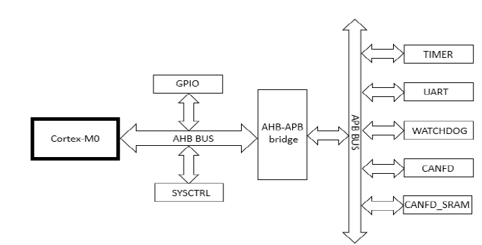
Figure 1. SOC Architecture Based on Cortex-M0 Processor.
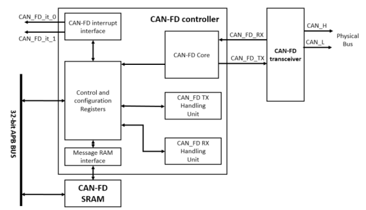
Figure 2. Structure of CAN-FD Protocol Controller.
III. Implementation
The design of the CAN-FD driver includes two aspects: the design and invocation of the function library and the design of the main function.The function library design involves writing various interface functions for easy direct invocation in embedded designs. The functional library design in this paper includes device initialization and information RAM address calculation; the main functional parts include sending and receiving CAN-FD frame data, printing information via serial ports, data storage, and system interrupts.The driver design concept is shown in Figure 3.
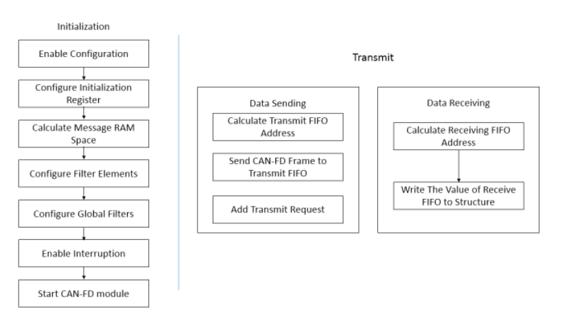
Figure 3. Design Concept of CAN-FD Device Driver.
By encapsulating other structure pointers with a single structure, resource management becomes easier. The main structure in this paper is as follows:
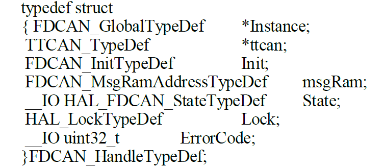
The above structure consists of a register table, initialization structure, message memory management structure, CAN-FD communication status structure, CAN-FD device lock structure, and CAN-FD error code. The design of the structure enhances the portability of the driver code, making it more convenient to call function structure members, thereby improving code readability. Simultaneously, other structure pointers are also encapsulated within this structure, such as the ‘FDCAN_GlobalTypeDef’ structure, which consists of:
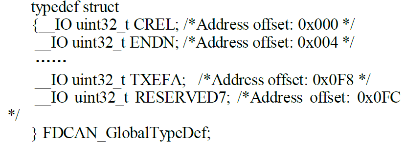
When the driver needs to configure a register of the CAN-FD device, it can be directly configured through this structure.
B. Driver Design
The design and compilation of the CAN-FD driver in this paper were completed in the Linux system environment, using the ARMCC compiler.
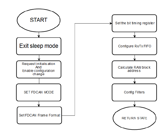
Figure 4. Initialization Process
· Initialization
Void FDCAN_init (int * btl)’ (the initialization function for the CAN-FD device) is used to configure the registers related to CAN-FD initialization,
including initializing frame format, node CAN-FD mode, nominal bit and data bit rates, receive and transmit FIFO, receive filters, etc. The initialization process is shown in Figure 4.
· Sending and Receiving
The CAN-FD driver can send and receive CAN-FD frames by calling ‘fdcan_tx (* databuf, len, ID, idtype, brs, fdform)’ and ‘fdcan_rx (* data)’.
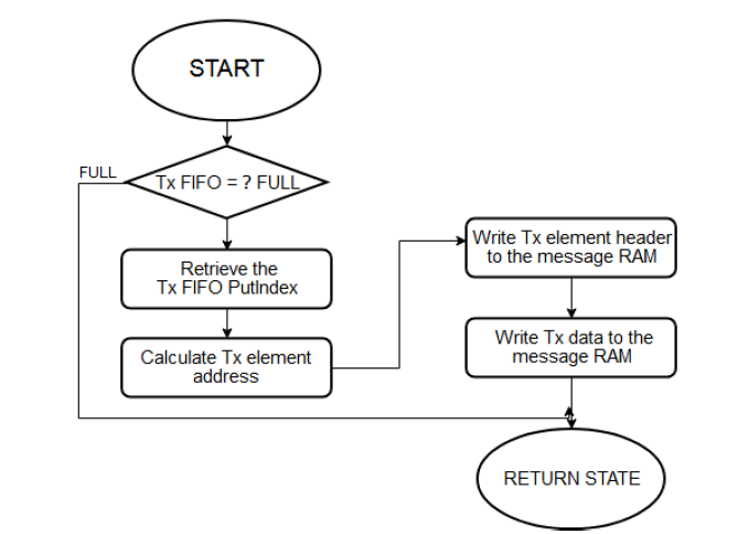
Figure 5. Sending Process of CAN-FD Frame.
The transmission function first configures the structure ‘FDCAN_TxHeaderTypeDef’ related to transmission, which contains the ID of the transmission frame, ID type, transmission frame type, data length, error status, speed change, transmission frame format, etc. Once the structure is configured, the CAN-FD frame and data to be sent are added to the transmit FIFO using the ‘AddMessageToTxFIFO’ function, along with the send command for the FIFO, waiting for the data to be sent. The ‘AddMessageToTxFIFO’ function first determines the size and address of the FIFO, then checks if the FIFO is full, adds the CAN-FD frame to the message RAM address of CAN-FD, and finally waits for the send request, achieving the sending of the CAN-FD frame. The sending process is shown in Figure 5. The transmission function designed in this paper allows for direct configuration of the CAN-FD frame format through parameters, making it easier to set up the sending of CAN-FD frames.
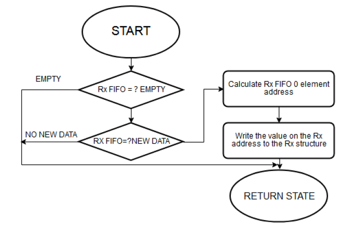
Figure 6. Receiving Process of CAN-FD Frame.
The receiving function transfers data from the receive FIFO address to an 8-bit array using the ‘GetRxMessage’ function, and then returns the array’s value to the main function.
Simultaneously, data is printed to the PC via the serial port, achieving data reception and visualization. The receiving process is shown in Figure 6.
C. Assembly
The compilation of the driver in this paper is completed by Makefile, which is related to the compilation rules of the entire project. The source files of the designed driver are organized into several directories by type, function, and module, with a series of rules defined by Makefile to specify the compilation process. The automatic compilation feature of Makefile allows the entire project to be compiled automatically with just the ‘make’ command, greatly improving the efficiency of driver development. The compilation process in this paper is shown in Figure 7 [6].
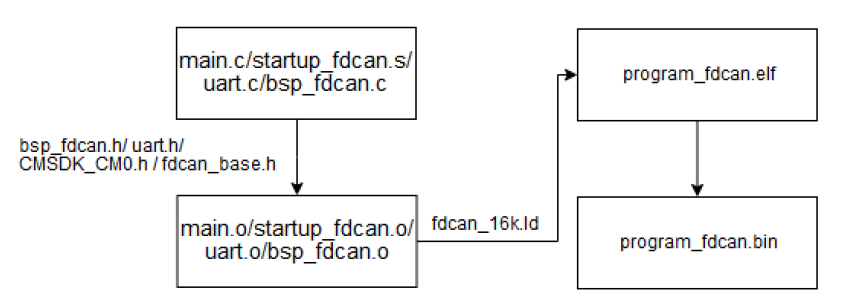
Figure 7. Compilation Process of Makefile.
The source files for the CAN-FD driver design include the main function (main.c), driver function library (bsp_fdcan.c/uart.c), CAN-FD structures and related macro definitions (fdcan_base.h), and the Cortex-M0 header file (CMSDK_CM0.h). The files used for compilation include Makefile and the linking script fdcan_16k.ld.
IV. Communication Testing
The environment for the CAN-FD bus communication simulation test is shown in Figure 8, including the j-link for burning the driver, the logic analyzer for capturing the CAN-FD frame waveform on the physical bus, the CAN-FD analyzer, UART serial port, and the CAN-FD bus controller SOC chip based on the Cortex-M0 core.
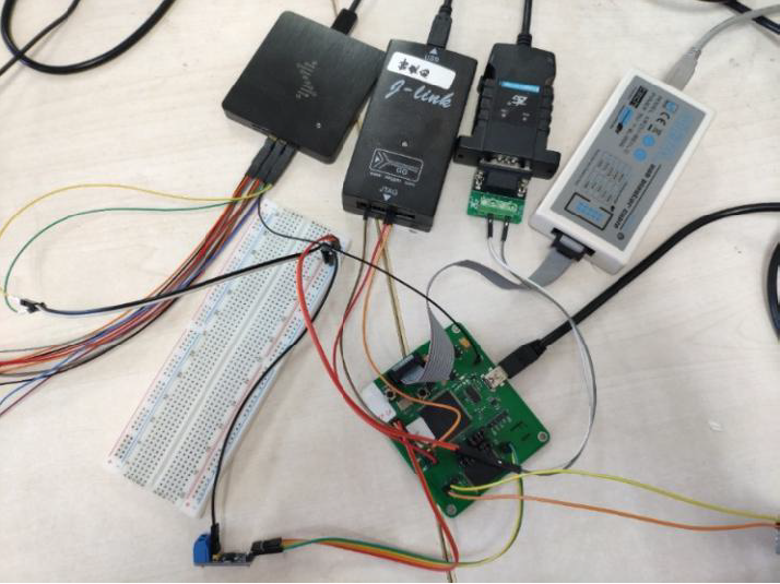
Figure 8. CAN-FD Communication Testing Environment.
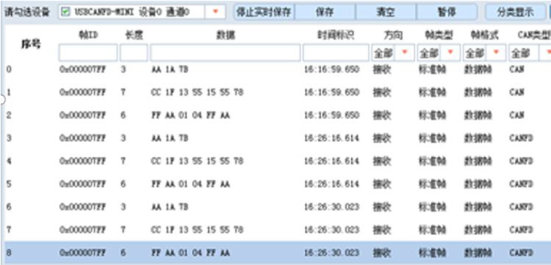
Figure 9. Transceiver Test of ZCANPRO.
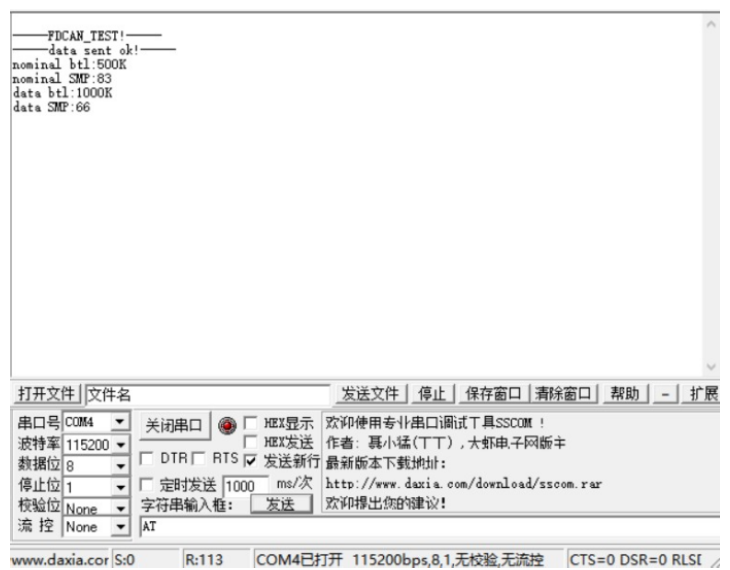
Figure 10. UART Information.
Open the upper computer software ZCANPRO to view the frames received by the CAN-FD analyzer on the physical bus, and use the serial port debugging tool sscom42 to view the printed information from UART, as shown in Figures 9 and 10.
V. Conclusion
This paper introduces the design and implementation of the CAN-FD protocol controller based on the Cortex-M0 processor.
Regarding the driver for CAN-FD devices, a CAN-FD device structure installed on the APB bus was designed, and functions for initializing the device and data transmission and reception were compiled, completing the driver design for the CAN-FD protocol controller, achieving data transmission based on the CAN-FD protocol, and completing board-level debugging of the device. With the widespread application of embedded systems and the high-performance CAN-FD bus, we believe that embedded systems for CAN-FD devices will see increasingly widespread application.
References:
[1]Robert I. Davis, Alan Burns, Reinder J. Controller Area Network (CAN) schedulability analysis: Refuted, revisited and revised[J]. Real-Time Systems. 2007 (3).
[2]Xie Yong, Huang Pengcheng, Comparison between CAN and CAN FD: A quantified approach[J]. International Conference on Ubiquitous Computing and Communications, 2017, p 1399-1403.
[3]Agrawal Megha, Huang Tianxiang. CAN-FD-Sec: Improving Security of CAN-FD Protocol[J]. Lecture Notes in Computer Science. v 11552 LNCS, p 77-93, 2019.
[4]PraKash Rashinkar, Peter Paterson, Leena Singh. System-On-a-chip verification methodology.
[5]Bricaud P J. IP Reuse Creation for System-on-a-chip Design[J]. Proceeding of the IEEE Custom Integrated Circuits, 1999, 27(5): 390-405.
[6]Simões Alberto, Fonseca, R ú ben. Makefile: Parallel dependency specification language[J]. Lecture Notes in Computer Science. v 4641 LNCS, p 33-41, 2007.
Sharing is not easy, please click 【👍】 and 【View】