Follow and star our official account for exciting content

Source: Quanran Electronics
Compiled by: Li Xiaoyao
There are already many tutorials on the QP event state machine framework, and with the availability of Chinese version books, learning QP can be relatively quick. However, experienced engineers may be too busy with work to learn more technologies. The benefits of using the QP framework may not entice you, but what if there is a graphical editing software that can automatically generate code? Wouldn’t that be tempting? Although it cannot completely replace coding, at least the application layer can be fully developed using this software. I would like to recommend QM software, a graphical programming software for state machines based on the QP framework and UML language. Below is a basic tutorial on how I used QM to develop the official Blinky example.
Introduction
QP, developed by Quantum Leaps, is an event-driven state machine framework that differs from traditional sequential systems (main + ISR) and traditional multitasking systems (operating systems). It enables object-oriented programming in C language and supports finite state machines (FSM) and hierarchical state machines (HSM).
The general framework of QP is shown in the figure below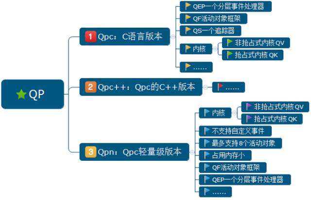 The development steps for developers using this framework are as follows:
-
Understand the overall project requirements -
Create a sequence diagram, identify active objects with behaviors, and allocate system resources to each active object to reduce coupling between objects, organizing event exchanges between various active objects -
Enumerate signals and events, event exchanges between active objects, and triggered signal events under each object. Signals are triggered events, while events carry parameters, such as serial port reception, which not only has the reception event but also the accompanying data -
Implement specific state machines for each active object -
Initialize and start the application program, allocate memory for the event queue, initialize active object priorities, and finally start QP to hand over control to QP for management. QP will execute the state machines under each active object based on your event triggers -
Debugging
As shown in the figure below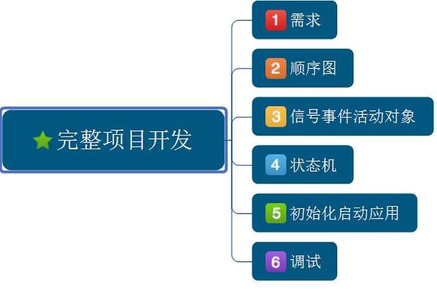 For more information about QP, please visit this link, which contains an electronic version of the PSiCC2-CN document that provides a detailed introduction to the entire QP framework
QpNano
Next, I will briefly introduce QpNano, as my modeling uses QpNano. It is a trimmed version of the event-driven framework, specifically designed for resource-limited microcontrollers, such as low-end 8-bit and 16-bit microcontrollers like 8051, PIC, AVR, MSP, STM8, and it is also suitable for 32-bit processors.
Next, I will introduce how to use the QP official Blinky example on the StateMachines board, but first, let’s briefly introduce the resources of the StateMachines board:
-
Using STM32F030C8T6 Cortex-M0 processor -
Onboard buttons, 12864 LCD screen, font library, digital tube, serial to USB, LED lights
After briefly introducing QP and QpNano, here are the main reasons I recommend using the QP framework. The QP framework allows for complete manual programming and the use of automated code generation tools like QM. QM (QP™ Modeler) is a graphical automatic code generation tool based on the QP framework and hierarchical state machine UML language, allowing the implementation of state machines and event exchanges for various objects using UML graphics, truly enabling graphical programming at the application layer, which is more suited to our programming mindset.
The Blinky example is a simple LED blinking program and is the most basic example for learning QP and QM. Below are the steps to establish the Blinky model using qm_3.3.0-win64:
Step 1: Create a new project in QM
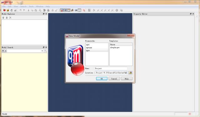
As shown in the figure below, click on New Model under the File menu to create a new QM project. Then, in the pop-up page, select qpn as the framework under Frameworks, choose None for Templates, name it Project, and select the location for saving the project.
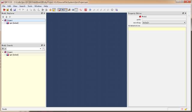
After clicking OK, you can see that the Project has been generated as shown in the figure below
Step 2: Create Objects
In the previous step, right-click on Project under Mode Explorer in the upper left corner to select Add Package to create a package. In the Property Editor, name it AOs, and select components as the stereotype as shown in the figure below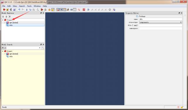 Then, right-click on AOs and select Add Class to create a class. In the Property Editor, name it Blinky, and select qpn::QActive as the superclass, as shown in the figure below
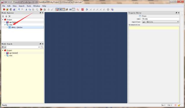 Next, right-click on AOs and select Add Attribute to add an attribute. In the Property Editor, name it AO_Blinky, and set the type to struct Blinky, which is the specific instance object of the Blinky class, as shown in the figure below
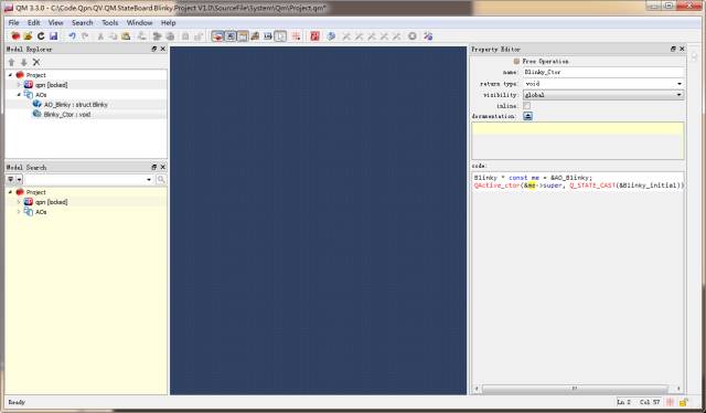
 Then, right-click on AOs and select Add Operation to add a class constructor. In the Property Editor, name it Blinky_Ctor, and select void for return type, and add the constructor code below
Blinky * const me = &AO_Blinky; QActive_ctor(&me->super, Q_STATE_CAST(&Blinky_initial));// This is an API function provided by the qpn framework for class constructionQ_STATE_CAST(&Blinky_initial) specifies the initial state as Blinky_initial, as shown in the figure below
Step 3: Create a State Machine for the Object
In the previous step, right-click on the Blinky class and select Add State Machine to create a state machine, then double-click on SM as shown in the figure below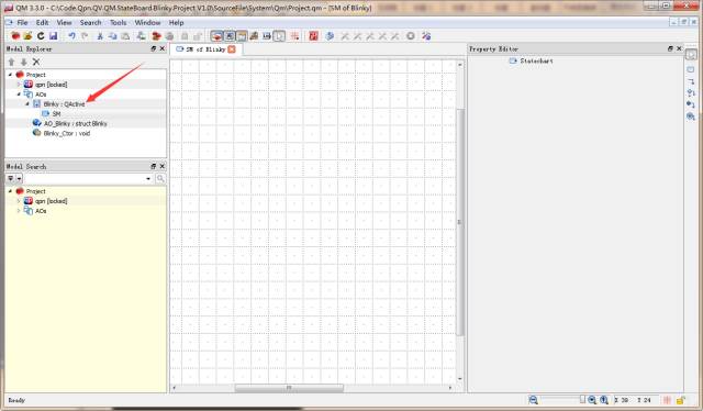 You will see a state machine workspace with a grid pop up, and the workspace size can be stretched from the bottom right corner of the grid.
Step 4: Draw the Specific State Implementation Diagram
In the previous step, a state machine was already created in the class. Now we need to implement the specific state diagram. The LED blinking program is very simple, with two states: on and off, triggered by a delay event. The two states only wait for the delay event, and once the delay event is triggered, they execute the actions of turning the light on and off.
As shown in the figure below, there is a small wide box on the right representing the state
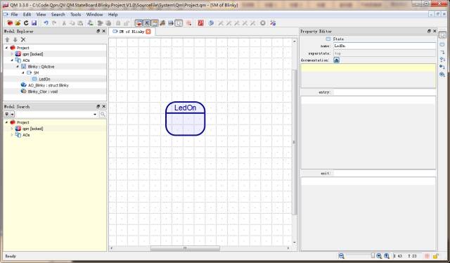
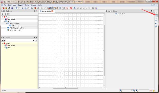 Click on this state icon to create a state in the workspace, and in the Property Editor, name it LedOn as shown in the figure below
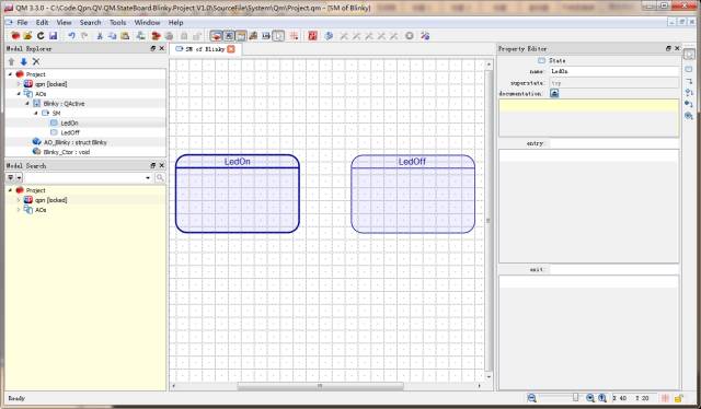
 Similarly, create the second state LedOff, as shown in the figure below
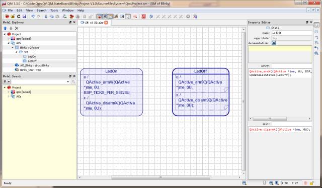
 Then click on the LedOn state diagram, and in the Property Editor, add code in the entry event processing of the state machine
QActive_armX((QActive *)me, 0U, BSP_TICKS_PER_SEC/8U, 0);And add the state change function UpdataLesState(LedOn); in the exit event processing of the state machine
QActive_disarmX((QActive *)me, 0U);QActive_armX((QActive *)me, 0U, BSP_TICKS_PER_SEC/8U, 0) is an API function provided by the qpn framework used to generate (BSP_TICKS_PER_SEC/8U) ticks of delay, where BSP_TICKS_PER_SEC is the number of ticks defined per second by the board, i.e., the heartbeat clock.
QActive_disarmX((QActive *)me, 0U); is also an API function provided by the qpn framework used to cancel the delay. The same method applies to LedOff; just change the entry event of the Led state to LedOff.
As shown in the figure below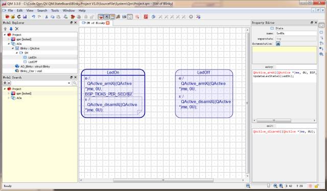
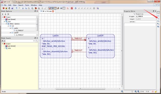
 Next, we need to establish transitions between the two states. Similarly, there is a Transition icon below the state machine icon on the right that represents state transition migration. The transition from LedOn state to LedOff state is a delay event, as the qpn framework provides a delay event enumeration called Q_TIMEOUT, which can be used directly. Click the icon and stretch from LedOn to LedOff state, and set the trigger in the property editor to Q_TIMEOUT as shown in the figure below
 Finally, you need to specify an initial transition for the state machine under the object, indicating which state it initializes to. Click the right icon for Initial Transition and set it to transition to the LedOn state as shown in the figure below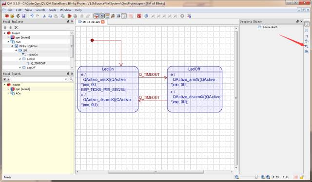
Step 5: Generate C Code
First, you need to create a file to declare and define the object. In the Model Explorer, right-click and select Add Directory. In the Property Editor, specify the path for the directory; I named it Code (by default, it is created under the project file directory). Then, in the Model Explorer, you can see the Code option. Right-click and select Add File, and in the Property Editor, name it Blinky.c. Similarly, create the file Project.h, which is mainly used for event enumeration, including external .h files used, and external object declarations.
As shown in the figure below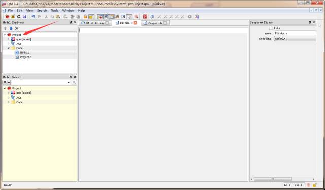
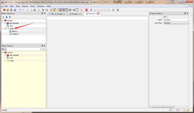 Next, define and declare the Blinky object and initialization in Blinky.c. QM has the following code generation directives:$declare() Declaration$define() Definition
As shown in the figure below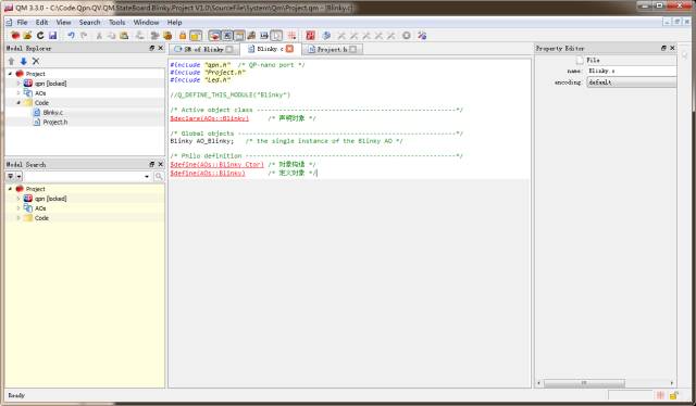
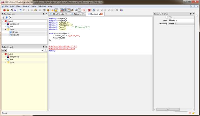 Finally, click Tools on the toolbar to select Generate Code or press F7 directly to generate C code
Step 6: Integrate the Generated Code into the Project
First, you need to port qpn to STM32F030. I used the qpn cooperative kernel, which only requires adding the qpn timing service API QF_tickXISR(0) in SysTick_Handler and adding the SysTick configuration interrupt time and priority in the QF_onStartup() function.
As shown in the figure below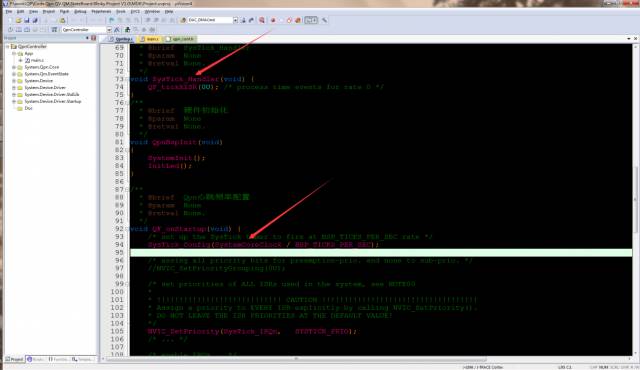 Next, allocate memory for the event queue for the Blinky object and specify the total number of active objects used in the entire project. This example only has one, which is configured in the macro definition QF_MAX_ACTIVE in #include “qpn_conf.h”.
As shown in the figure below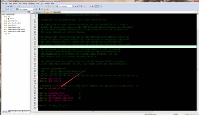
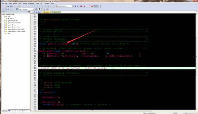 The entire Blinky QM modeling consists of:
-
Step 1: Create a new project in QM -
Step 2: Create Objects -
Step 3: Create a State Machine for the Object -
Step 4: Draw the Specific State Implementation Diagram -
Step 5: Generate C Code -
Step 6: Integrate the Generated Code into the Project
With this introduction, it seems that generating a very simple blinking light program with QM is quite time-consuming, and it might be faster to write a few lines of code manually. However, this is a leap forward; the logical code layer is entirely implemented graphically, meaning that in the future, different complex projects can be managed using graphics, which are easier to understand and maintain than code. Graphical programming is the future direction.
Embedded Programming Series
Linux Learning Series
C/C++ Programming Series
Qt Advanced Learning Series
Follow my WeChat public account and reply “Join Group” to join the technical exchange group according to the rules.
Click on “Read Original” for more sharing.