Click the card below to follow Arm Technology Academy
A few days ago, a customer asked a question: If the frequency of external interrupts is fast enough, how should new interrupts be handled if the previous interrupt has not been processed?
After researching the official ARM manual, I learned about the ways to enable, clear, or suspend interrupts, and today I will share it with everyone.
Interrupts are generally generated by hardware (such as peripherals, external pins). When a certain internal or external event occurs, the MCU’s interrupt system forces the CPU to pause the currently executing program to handle the interrupt event. After the interrupt is handled, it returns to the point where the program was interrupted and continues execution. All Cortex-M core systems have a component called NVIC for interrupt handling, which is mainly responsible for handling interrupts and other events that require service. The Nested Vectored Interrupt Controller (NVIC) is integrated into the Cortex-M0 processor, closely linked to the processor core, and provides interrupt control functionality as well as support for system exceptions.
The NVIC in the processor can handle multiple maskable interrupt channels and programmable priorities. Interrupt input requests can be level-triggered or pulse signals of at least one clock cycle. Each external interrupt line can be independently enabled, cleared, or suspended, and the suspended state can also be set and cleared manually.
When the main program is executing and encounters an Interrupt Request (IRQ), it pauses the execution of the main program and executes the Interrupt Service Routine (ISR), which is called a response. After the ISR finishes executing, it returns to the breakpoint of the main program and continues executing the main program. Multiple interrupts can be nested. A lower-priority interrupt being executed can be interrupted by a higher-priority interrupt, and after the high-priority interrupt is executed, it returns to the low-priority interrupt to continue execution, adopting a “tail-chaining interrupt” mechanism.
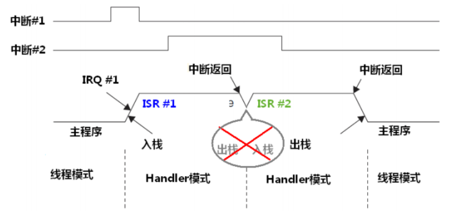
Kernel interrupts (exception management and sleep modes, etc.) are prioritized by the SCB register, while IRQ interrupt priorities are managed by the NVIC.
The NVIC registers are memory-mapped, with the starting address of its registers being 0xE000E100, and access must be 32 bits each time.
The starting address of the SCB register is 0xE000ED00, also accessed in 32 bits each time. The SCB register mainly includes SysTick operations, exception management, and sleep mode control.
NVIC has the following features:
-
Flexible interrupt management: enable/clear, priority configuration
-
Hardware nested interrupt support
-
Vectorized exception entry
-
Interrupt masking
1. Interrupt Enable and Clear Interrupt
ARM divides the interrupt enable and clear setting registers of the processor into two different addresses. This design has the following advantages: on one hand, this method reduces the steps required to enable interrupts. To enable an interrupt, NVIC only needs to be accessed once, which also reduces program code and execution time. On the other hand, when multiple application processes access the register simultaneously or during read/write operations, it may operate on other interrupt enable bits, which could lead to register loss. Separating the set and clear into two registers can effectively prevent control signal loss.
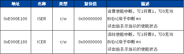
Therefore, I can independently operate the enable and clear settings of each interrupt.
1.1. C Code
*(volatile unsigned long) (0xE000E100) = 0x4 ; // Enable interrupt #2
*(volatile unsigned long) (0xE000E180) = 0x4 ; // Clear interrupt #2
1.2. Assembly Code
__asm void Interrupt_Enable()
{
 LDR R0, =0xE000E100  ;  // Address of ISER register
 MOVS R1, #04         ;  // Set interrupt #2
 STR R1, [R0]         ;  // Enable interrupt #2
}

__asm void Interrupt_Disable()
{
 LDR R0, =0xE000E180  ;  // Address of ICER register
 MOVS R1, #04         ;  // Set interrupt #2
 STR R1, [R0]         ;  // Enable interrupt #2
}
1.3. CMSIS Standard Device Driver Functions
// Enable interrupt #IRQn
__STATIC_INLINE void __NVIC_EnableIRQ(IRQn_Type IRQn)
{
    if ((int32_t)(IRQn) >= 0) {
        NVIC->ISER[0U] = (uint32_t)(1UL << (((uint32_t)(int32_t)IRQn) & 0x1FUL));
    }
}
// Clear interrupt #IRQn
__STATIC_INLINE void __NVIC_DisableIRQ(IRQn_Type IRQn)
{
    if ((int32_t)(IRQn) >= 0) {
        NVIC->ICER[0U] = (uint32_t)(1UL << (((uint32_t)(int32_t)IRQn) & 0x1FUL));
        __DSB();
        __ISB();
    }
}
// Read enabled interrupt #IRQn
__STATIC_INLINE uint32_t __NVIC_GetEnableIRQ(IRQn_Type IRQn)
{
    if ((int32_t)(IRQn) >= 0) {
        return((uint32_t)(((NVIC->ISER[0U] & (1UL << (((uint32_t)(int32_t)IRQn) & 0x1FUL))) != 0UL) ? 1UL : 0UL));
    }
    else {
        return(0U);
    }
}
2. Interrupt Suspend and Clear Suspend
If an interrupt occurs but cannot be processed immediately, the interrupt request will be suspended. The suspended state is stored in a register, and if the current priority of the processor has not yet decreased to handle the suspended request and the suspended state has not been manually cleared, this state will remain.
Interrupts can be accessed or modified by operating on two independent registers for setting suspend and clearing suspend. The interrupt suspend register is also implemented by two addresses to set and clear relevant bits. This allows each bit to be modified independently without worrying about data loss when two application processes compete for access.
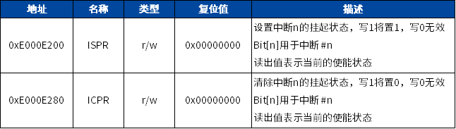
The interrupt suspend state register allows software to trigger interrupts. If the interrupt has been enabled and not masked, and no higher-priority interrupts are currently running, the interrupt service routine will be executed immediately.
2.1. C Code
*(volatile unsigned long)(0xE000E100) = 0x4 ; // Enable interrupt #2
*(volatile unsigned long)(0xE000E200) = 0x4 ; // Suspend interrupt #2
*(volatile unsigned long)(0xE000E280) = 0x4 ; // Clear the suspend state of interrupt #2
2.2. Assembly Code
__asm void Interrupt_Set_Pending()
{
 LDR R0, =0xE000E100   ;  // Set enable interrupt register address
 MOVS R1, #0x4         ;  // Interrupt #2
 STR R1, [R0]          ;  // Enable interrupt #2
 LDR R0, =0xE000E200   ; // Set suspend interrupt register address
 MOVS R1, #0x4         ;  // Interrupt #2
 STR R1, [R0]          ;  // Suspend interrupt #2
}

__asm void Interrupt_Clear_Pending()
{
 LDR R0, =0xE000E100   ;  // Set enable interrupt register address
 MOVS R1, #0x4         ;  // Interrupt #2
 STR R1, [R0]          ;  // Enable interrupt #2
 LDR R0, =0xE000E280   ; // Set clear interrupt pending register address
 MOVS R1, #0x4         ;  // Interrupt #2
 STR R1, [R0]          ;  // Clear the pending state of interrupt #2
}
2.3. CMSIS Standard Device Driver Functions
// Set an interrupt pending
__STATIC_INLINE void __NVIC_SetPendingIRQ(IRQn_Type IRQn)
{
    if ((int32_t)(IRQn) >= 0) {
        NVIC->ISPR[0U] = (uint32_t)(1UL << (((uint32_t)(int32_t)IRQn) & 0x1FUL));
    }
}

// Clear interrupt pending
__STATIC_INLINE void __NVIC_ClearPendingIRQ(IRQn_Type IRQn)
{
    if ((int32_t)(IRQn) >= 0) {
        NVIC->ICPR[0U] = (uint32_t)(1UL << (((uint32_t)(int32_t)IRQn) & 0x1FUL));
    }
}

// Read interrupt pending state
__STATIC_INLINE uint32_t __NVIC_GetPendingIRQ(IRQn_Type IRQn)
{
    if ((int32_t)(IRQn) >= 0) {
        return((uint32_t)(((NVIC->ISPR[0U] & (1UL << (((uint32_t)(int32_t)IRQn) & 0x1FUL))) != 0UL) ? 1UL : 0UL));
    }
    else {
        return(0U);
    }
}
NVIC belongs to the processor core part, so it is only briefly mentioned in the user manual of the MM32 MCU chip, without detailed discussion. To deeply understand the relevant registers and functions, refer to the “Cortex-M0 Technical Reference Manual”.
In the next chapter, we will learn about the implementation of interrupt priority.
Recommended Reading
-
【Repeated Hops】Transformation Journey from AC5 to AC6 (2) – “Cheese Sandwich Stack Model”
-
Detailed Explanation of SOC Multi-core Startup Process
-
【Repeated Hops】Transformation Journey from AC5 to AC6 (1) – Remediation and Preparation
Follow Arm Technology Academy