The main purpose of thermal management is to ensure that all electronic components, especially BGA, are maintained within their functional and maximum allowable limits. The functional temperature limit defines the range of environmental temperatures or component package temperatures that allow electronic circuits to operate normally.
It is essential to understand the cooling technologies that the printed circuit board (PCB) components will employ to ensure reasonable design. For commercial applications, direct air cooling systems (i.e., cooling air in contact with PCB components) are typically used.
In harsher environments, other cooling systems must be used to cool the PCB components. In such applications, components are installed in structures cooled by air or liquid, and PCB components are cooled through surface heat exchange and conduction. These designs must utilize appropriate metal heat sinks on the PCB components. Proper component installation and bonding are also required. To ensure a well-designed system, thermal dissipation diagrams should be provided to assist in analysis and thermal design for the PCB components.
There are three basic modes of heat transfer within electronic devices: conduction, convection, and radiation. These modes of heat transfer often interact simultaneously. Therefore, any thermal management method should aim to maximize their natural interactions.
1. Conduction
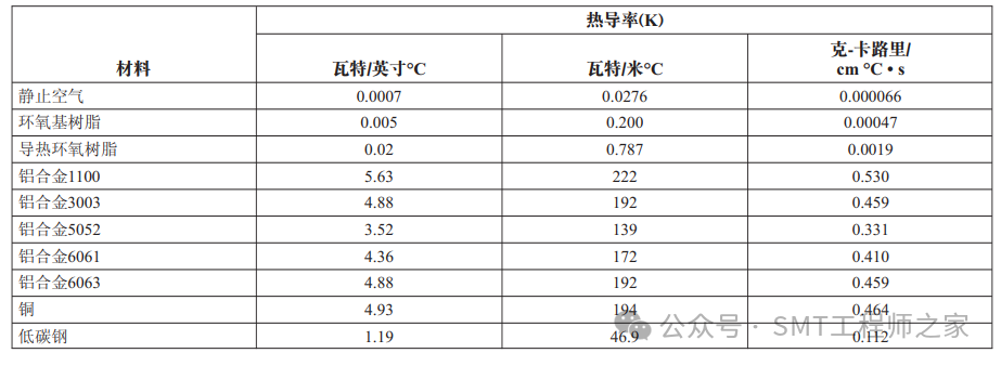
All materials conduct heat to some extent. The amount of heat conducted through a material is proportional to the material’s thermal conductivity K, the cross-sectional area of the conduction path, and the temperature difference between the materials. Heat conduction is inversely proportional to the length of the path and the thickness of the material (see the table below).
2. Radiation
Heat radiation is the transfer of heat through electromagnetic radiation, primarily in the infrared (IR) wavelength. It is the only method of heat transfer in a vacuum, such as in space environments.
Heat transfer by radiation is a function of the surface emissivity of the heat source, its effective surface area, and the fourth power difference of the absolute temperatures between the objects.
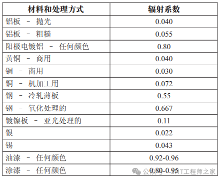
The emissivity is the ratio of the energy radiated by a material to the energy radiated by a black body at the same temperature with an emissivity of 1. The optical color of an object has little relation to its “thermal black body” characteristics. Regardless of whether it is black, red, or blue, the emissivity of anodized aluminum does not change. However, surface finish is crucial. Matte or dull surfaces radiate heat more effectively than bright or shiny surfaces (see the table below).
3. Convection
The convection heat transfer mode is the most complex. It involves the molecular motion of fluids, typically air.
The rate of heat flow due to convection from an object to a fluid is a function of the object’s surface area, temperature difference, fluid velocity, and certain properties of the fluid.
Any fluid in contact with a hotter surface will decrease in density and rise, a phenomenon known as “free” or “natural” convection. Air movement can be induced by this phenomenon or by some external artificial devices, such as fans or blowers. Forced convection can be ten times more efficient than natural convection.
4. Thermal Interface Materials
Heat sinks installed on BGAs are the most common technique for cooling silicon chip devices within BGA packages. The thermal interface materials required for these heat sinks are placed between the heat sink and the BGA to allow heat to conduct from the top surface of the package to the bottom surface of the heat sink.
Components that are in close proximity will absorb each other’s radiated energy. If thermal radiation is the primary mode of heat transfer, the “hot” spots between components must be isolated.
When selecting thermal interface materials, attention must be paid to the flatness of the surfaces of the BGA and the heat sink.Warpage of the BGA package during the reflow soldering process and large tolerances in the contact surface of the heat sink can lead to significant gaps, making it difficult for the interface material to fill reliably, resulting in poor thermal performance and/or weak connections of the heat sink.
There are various types of thermal interface materials (TIMs), as described below.
1. Adhesives
Metal-filled epoxy resins and silicone adhesives were among the first widely used TIMs. They serve a dual purpose as TIM interface materials and mechanical bonding materials, as they achieve high-strength bonding through complete cross-linking upon curing. Therefore, unlike other TIMs, mechanical bonding is not necessary when using adhesives. The downside of adhesives is that they require thermal curing after the BGA is soldered to the PCB, and there may be significant delamination at the adhesive interface due to mismatched thermal expansion coefficients between the heat sink and the package. Another subclass of adhesives is pressure-sensitive adhesives (PSAs), which do not require curing to create a bonding interface but do require a certain amount of pressure, typically in the range of 20 to 30 psi. Their application in BGAs is therefore limited, as improper control may adversely affect the BGA solder joints.
2. Thermal Grease
Thermal grease is a metal-filled polymer that has the inherent advantage of a viscous liquid, allowing it to adapt to the macro and micro irregularities of the surfaces between BGA components and heat sinks. Unlike adhesives, they have excellent thermal performance and do not require curing. The main drawback of thermal grease is that over time, they tend to flow out from between the heat sink and the package. This phenomenon, known as “pump-out,” is caused by mechanical thermal stress acting on the adhesive interface during temperature cycling.
3. Phase Change Materials (PCM)
Phase change materials are solid at room temperature but turn into liquid when the temperature rises due to heat conduction from the BGA surface. Because they are typically in film form and do not require curing, they are convenient to operate and apply. However, their thermal conductivity is inferior to that of thermal grease, adhesives, and other TIM alternatives, making them suitable only for low-power devices.
4. Gels
Gels consist of lightly cross-linked silicone polymers filled with metal or ceramic particles to achieve the desired thermal conductivity of TIM. Gels combine the advantages of thermal grease and cured adhesives, as they do not pump out and do not require curing. Their lower modulus reduces thermal mechanical stress and avoids delamination at the bonding interface. They have a high volumetric thermal conductivity and have been applied in BGAs, including cooling for high-power CPU devices.
5. Thermal Adhesive Tapes
Thermal adhesive tapes can occasionally be used to provide the necessary thermal conductivity for BGA cooling. This type of thermal interface material has gradually gained widespread use due to its ease of operation, as it can simply be adhered to the surface of the BGA device that needs cooling.
5. BGA Heat Sink Connection Methods
There are several methods for connecting heat sinks to BGAs, as detailed in the illustrations below. Figure 1 shows a heat sink connected to the top of a BGA package using thermal adhesive. This adhesive serves as both a thermal conduction medium and a mechanical bonding medium. However, as mentioned above, this technique requires thermal curing after soldering to achieve the cross-linking and hardening of the adhesive.
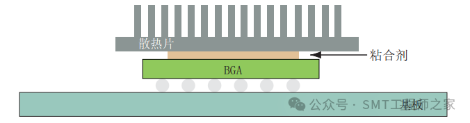
Figure 2 illustrates a heat sink fixed to the BGA substrate and connected to the top of the BGA package using hooks. However, there is a risk of damaging the solder joints when installing the hooks. The thermal interface materials used in this method are thermal grease, PCM, or gels, which do not require strong mechanical connections between the heat sink and the top of the BGA package. A disadvantage of this method is that the weight of the heat sink is borne by the package, and during mechanical shock and vibration, the BGA solder balls must withstand the mechanical stress caused by the additional mass of the heat sink.
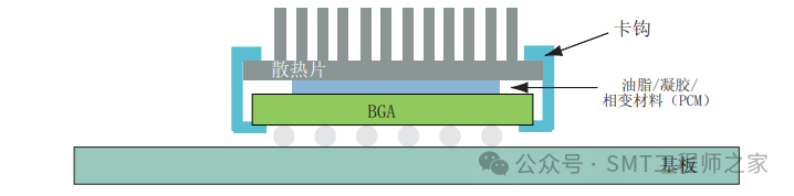
Figure 3 shows a heat sink connected to the BGA through hooks fixed in holes in the printed circuit board. These small holes do not require plating. Unlike the previous case, when the hooks are engaged, the printed circuit board supports the weight of the heat sink, but some stress is still transmitted to the BGA solder balls during mechanical shock and vibration. Additionally, when the component is placed vertically, the heat sink exerts a cantilever load on the solder joints, which can lead to early failure of the solder joints.
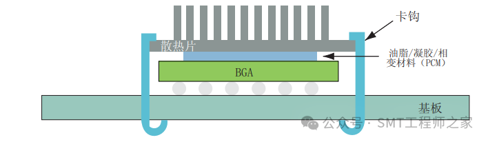
Figure 4 shows a connection method where a pillar soldered to the printed circuit board is fixed with hooks and connects to the top of the BGA heat sink. During mechanical shock and vibration, this connection method transmits less stress to the BGA solder balls than the previous methods. However, the solder joints of the pillar must bear most of the stress.
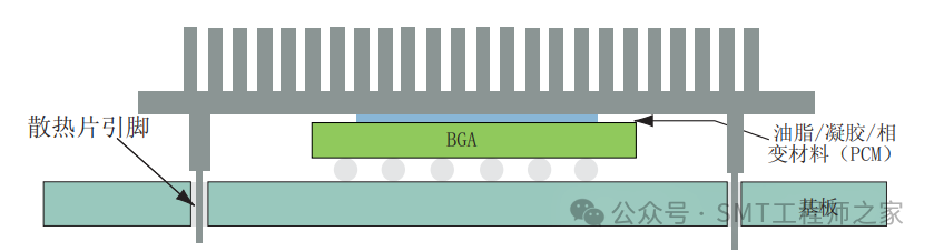
Figure 5 shows a heat sink connected directly to the printed circuit board through wave soldering. This heat sink design has four or more pins that are inserted into the holes of the board before wave soldering. Unlike the previous methods, this method does not require any post-assembly processing to connect the heat sink.
The three methods shown in Figures 3, 4, and 5 have a disadvantage that does not occur in the first two methods: these methods require the printed circuit board to be designed with mounting holes, which may reduce the space available for routing on various layers of the circuit board. For high-density board designs, this may affect the final layer count of the circuit board.