Compilation of Electromagnetic Knowledge for High School Students

Knowledge Group 1: Magnetic Phenomena and Magnetic Fields

1. Magnetic Phenomena and the Magnetic Effect of Electric Current

1. Magnetic Phenomena

(1) Magnetism and Magnets
An object that has the property of attracting iron, cobalt, nickel, and other materials is called magnetic. Objects with magnetic properties are called magnets.
(2) Magnetic Poles
The magnetic strength varies in different parts of a magnet, and the area with the strongest magnetism is called a magnetic pole. Every magnet has two magnetic poles, one called the south pole (also known as the S pole) and the other called the north pole (also known as the N pole).
(3) Interaction Between Magnetic Poles
Like poles repel each other, while unlike poles attract each other.
(4) Magnetization and Demagnetization
The process of making an originally non-magnetic object acquire magnetic properties is called magnetization; conversely, the process of a magnetized object losing its magnetic properties is called demagnetization.
(5) Magnetic Materials
Magnetic materials are composed of ferromagnetic or ferrimagnetic substances, such as iron, cobalt, and nickel. They are generally divided into two categories: soft magnetic materials and hard magnetic materials. Soft magnetic materials are those that can be easily demagnetized after magnetization, while hard magnetic materials are those that are not easily demagnetized.
[Note] The magnetic pole of a magnetized object is opposite to the magnetic pole of the magnet that magnetized it.

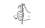
2. The Magnetic Effect of Electric Current

(1) Oersted Experiment
Compilation of Electromagnetic Knowledge for High School Students
In 1820, Danish physicist Oersted discovered that when a wire carrying current is placed in the north-south direction, a small magnetic needle placed parallel to the wire below it will deflect.
Oersted’s experiment significance: discovered the magnetic effect of electric current, revealing the connection between electricity and magnetism for the first time.
[Note] During the Oersted experiment, to reduce the influence of the geomagnetic field, the current-carrying wire should be placed in the north-south direction and directly above or below the small magnetic needle (the needle should not be placed along the extension of the wire). Since the small magnetic needle points north-south when at rest, if the wire is placed east-west, the needle may not deflect.
(3) The Magnetic Effect of Electric Current: There is a magnetic field around a current-carrying wire, meaning that the magnetic field of the current causes a magnetic needle placed around the wire to deflect, and the direction of the magnetic field is related to the direction of the current; this phenomenon is called the magnetic effect of electric current.
(2) The Effect of a Magnet on a Current-Carrying Wire
As shown in the figure, a magnet exerts a force on a current-carrying conductor rod, causing the rod to move.
Compilation of Electromagnetic Knowledge for High School Students
(3) Interaction Between Currents
As shown in the figure, when two parallel wires carrying current are close to each other, if the currents are in the same direction, the two wires will attract each other; if the currents are in opposite directions, the two wires will repel each other.
Compilation of Electromagnetic Knowledge for High School Students
Conclusion: Same direction currents attract each other, while opposite direction currents repel each other.

Knowledge Group 2: Magnetic Induction Intensity and Common Magnetic Fields

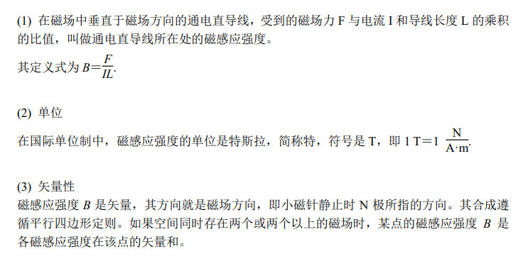
1. Magnetic Induction Intensity

1. Direction of Magnetic Induction Intensity

(1) Magnetic Induction Intensity
A physical quantity that describes the strength and direction of a magnetic field, represented by the symbol B.
(2) Direction of Magnetic Induction Intensity
The direction indicated by the north pole of a small magnetic needle at rest is the direction of magnetic induction intensity at that point, referred to as magnetic field direction. Regardless of whether the small magnetic needle is at rest, the direction of the force acting on its north pole is determined, thus the direction of the magnetic field can also be said to be the force direction on the north pole of the small magnetic needle in the magnetic field.

2. Magnitude of Magnetic Induction Intensity

Compilation of Electromagnetic Knowledge for High School Students

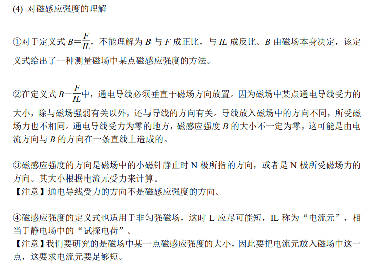
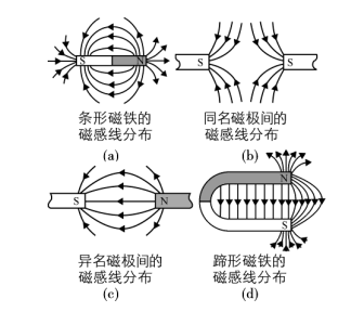
2. Magnetic Field Lines (Key Point)

1. Definition

Curves drawn in a magnetic field that have a direction, where the tangent direction at each point is the same as the magnetic field direction at that point, are called magnetic field lines.

2. Distribution of Magnetic Field Lines in Common Magnetic Fields

Compilation of Electromagnetic Knowledge for High School Students

3. Characteristics of Magnetic Field Lines

(1) Magnetic field lines outside the magnet emerge from the north pole (N pole) and enter the south pole (S pole), while inside the magnet they return from the south pole to the north pole, forming a closed curve.
(2) The density of magnetic field lines indicates the strength of the magnetic field. Areas where magnetic field lines are dense have a strong magnetic field, while areas where they are sparse have a weak magnetic field.
(3) The tangent direction at each point on a magnetic field line is the direction of the magnetic field at that point.
(4) Magnetic field lines are a set of directed curves imagined to study the magnetic field, and do not objectively exist as real curves in the magnetic field.
(5) Magnetic field lines do not intersect, touch, or break in space.
(6) The absence of magnetic field lines does not indicate that there is no magnetic field present; through any point in the magnetic field, it is always possible to draw a magnetic field line.

3. Common Magnetic Fields

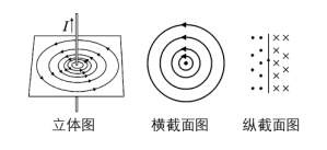
1. Magnetic Field of a Straight Electric Current (Key Point)

(1) Ampere’s Rule
Compilation of Electromagnetic Knowledge for High School Students
Hold the wire with your right hand, with your straight thumb pointing in the direction of the current; the direction indicated by your curled fingers is the direction of the magnetic field lines surrounding the wire, also known as the right-hand screw rule.
(2) Distribution Characteristics
(1) The three-dimensional and cross-sectional distribution of the magnetic field of a straight electric current is shown in the figure.
(2) The magnetic field lines around a current-carrying straight wire are concentric circles centered at each point on the wire, and the magnetic field of the current is a spatial figure.
(3) The magnetic field of a straight electric current has no magnetic poles.
(4) The strength of the magnetic field is related to the distance from the wire; the closer to the wire, the stronger the magnetic field; the farther from the wire, the weaker the magnetic field.
Compilation of Electromagnetic Knowledge for High School Students
[Note] In the figure, the “×” symbol indicates that the magnetic field direction is perpendicular to the paper surface and inward, while the “·” symbol indicates that the magnetic field direction is perpendicular to the paper surface and outward.

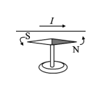
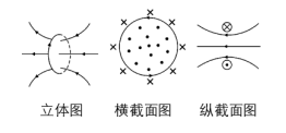
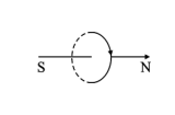
2. Magnetic Field of a Circular Electric Current (Key Point)

(1) Ampere’s Rule
Let the fingers of your right hand curve in the direction of the circular current, and the direction indicated by your straight thumb is the direction of the magnetic field lines along the axis of the circular wire, as shown in the figure.
Compilation of Electromagnetic Knowledge for High School Students
(2) Distribution Characteristics
(1) The three-dimensional and cross-sectional distribution of the magnetic field of a circular electric current is shown in the figure.
Compilation of Electromagnetic Knowledge for High School Students
(2) The magnetic field of a circular electric current is similar to that of a bar magnet, with its sides equivalent to the N pole and S pole.
(3) Since the magnetic field lines are closed curves, the number of magnetic field lines inside and outside the loop is equal, hence the magnetic field inside the loop is strong, while the magnetic field outside is weak.
(4) The magnetic field of a circular electric current can be seen as the superposition of the magnetic fields of many short straight currents on a microscopic level.

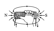
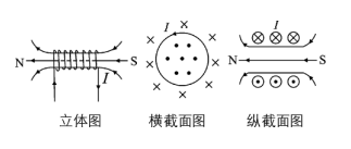
3. Magnetic Field of a Current-Carrying Solenoid (Key Point)

(1) Ampere’s Rule
Compilation of Electromagnetic Knowledge for High School Students
Use your right hand to grasp the solenoid, with the direction of your curled fingers aligned with the direction of the current; the direction indicated by your thumb is the direction of the magnetic field lines along the central axis of the solenoid (the thumb points towards the north pole of the solenoid), as shown in the figure.
(2) Distribution Characteristics
(1) The three-dimensional and cross-sectional distribution of the magnetic field of a current-carrying solenoid is shown in the figure.
Compilation of Electromagnetic Knowledge for High School Students
(2) Inside, it is approximately a uniform magnetic field that is stronger than outside, with the direction from the S pole to the N pole; outside, it is similar to a bar magnet, directed from the N pole to the S pole.
(3) A circular electric current can be thought of as a single turn of a current-carrying solenoid, while a current-carrying solenoid is composed of many turns of circular currents in series. Thus, the magnetic field of a current-carrying solenoid is the superposition of these circular current magnetic fields.
[Note] The uniform magnetic field added to the solenoid should be perpendicular to the plane of the D-shaped box.

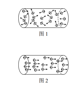
4. Ampere’s Molecular Current Hypothesis

(1) Content of Ampere’s Molecular Current Hypothesis
Compilation of Electromagnetic Knowledge for High School Students
Ampere believed that there exists a circular current—molecular current—within the particles of matter such as atoms and molecules. The molecular current makes each particle of matter act as a tiny magnet, with its two sides corresponding to two magnetic poles, as shown in the figure.
(2) Explanation of Some Magnetic Phenomena by Ampere’s Molecular Current Hypothesis
(1) Magnetization Phenomenon:
When an iron rod is not magnetized, the orientation of the molecular currents inside it is chaotic, and their magnetic fields cancel each other out, making it appear non-magnetic, as shown in Figure 1. When the iron rod is subjected to an external magnetic field, the orientations of the molecular currents become roughly the same, the iron rod gets magnetized, and its ends show a strong magnetic effect to the outside, forming magnetic poles, as shown in Figure 2.
Compilation of Electromagnetic Knowledge for High School Students
② Demagnetization of Magnets: When a magnet is subjected to high temperatures or violent impacts, the orientation of the molecular currents becomes chaotic again due to intense thermal motion or vibrations, causing the magnetic properties of the magnet to disappear.
(3) The Essence of Magnetic Phenomena
The magnetic field of a magnet and the magnetic field of electric current are both produced by moving charges.

4. Uniform Magnetic Field

1. Definition

In a certain region of a magnetic field, if the magnitude and direction of the magnetic induction intensity at all points are the same, this region’s magnetic field is called a uniform magnetic field.

2. Characteristics of Magnetic Field Lines

Parallel straight lines with equal spacing.

3. Locations of Existence
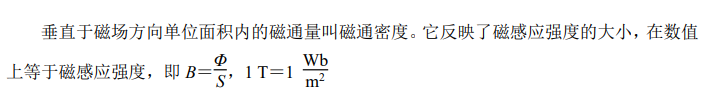
The magnetic field between two parallel unlike magnetic poles that are very close to each other (excluding edges) and inside a current-carrying solenoid (excluding edges) is a uniform magnetic field.

5. Magnetic Flux

1. Definition

Compilation of Electromagnetic Knowledge for High School Students
As shown in the figure, in a uniform magnetic field with magnetic induction intensity B, there is a plane perpendicular to the magnetic field direction with an area S. The product of B and S is called the magnetic flux through this area, abbreviated as magnetic flux. It is represented by the letter Φ.

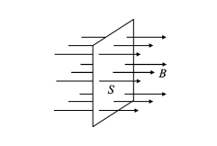
2. Calculation (Key Point)

(1) Formula: Φ=BS.
(2) Applicable Conditions: (1) Uniform magnetic field; (2) Magnetic field lines perpendicular to the plane.
Compilation of Electromagnetic Knowledge for High School Students
(3) If the magnetic field lines are not perpendicular to the plane, the formula Φ=BS should use the projection area of the plane in the direction perpendicular to the magnetic field lines, that is, Φ=BS⊥. As shown in the figure, in a vertical uniform magnetic field, if the plane abcd makes an angle θ with the plane perpendicular to the magnetic field lines, the magnetic flux through area abcd should be Φ=BScos θ, where Scos θ is the projection of area S in the direction perpendicular to the magnetic field lines.
(4) If the magnetic field lines pass through the same plane in opposite directions, and the number of magnetic field lines in the positive direction is Φ1 and in the negative direction is Φ2, then the magnetic flux equals the net number of magnetic field lines passing through the plane (the algebraic sum of magnetic flux, net magnetic flux), that is, Φ=Φ1−Φ2.
(5) Since magnetic field lines are closed curves (unlike electric field lines in electrostatics), the magnetic flux through any closed surface must be zero, that is, Φ=0. For example, in a spherical surface, as long as magnetic field lines pass into the sphere, they must also pass out of the sphere, resulting in a net magnetic flux of zero, that is, the magnetic flux is zero.
[Key Point] Magnetic flux is related to a specific surface and is independent of the number of turns in a given coil; that is, when calculating magnetic flux, as long as the area of the n-turn coil is the same and the placement is the same, the magnetic flux through the n-turn coil and the single-turn coil is the same, regardless of the number of turns n.

3. Units

Compilation of Electromagnetic Knowledge for High School Students

4. Magnetic Flux Density

Compilation of Electromagnetic Knowledge for High School Students

5. Positive and Negative Magnetic Flux

Magnetic flux is a scalar that can be positive or negative. The positive and negative values are defined as follows: any surface has a positive and negative side; if the magnetic field lines enter the positive side, the magnetic flux is positive; if the magnetic field lines enter from the negative side, the magnetic flux is negative.
[Note] The positive and negative values of magnetic flux do not indicate size or direction, but are introduced for calculation convenience.

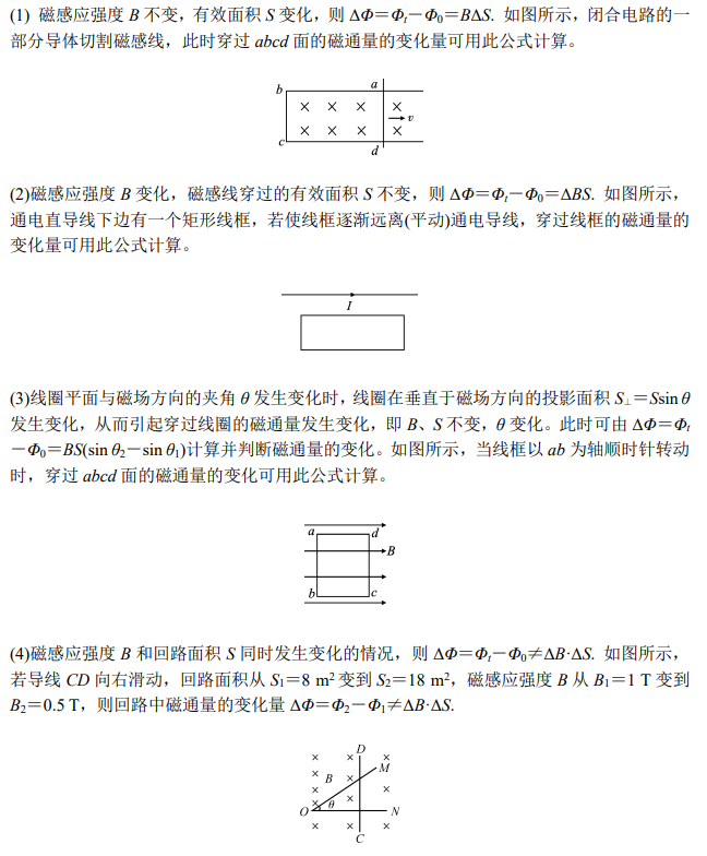
6. Several Situations of Changing Magnetic Flux

Compilation of Electromagnetic Knowledge for High School Students

Knowledge Group 3: Ampere’s Force and Lorentz Force

1. Ampere’s Force

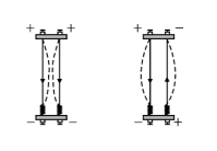
1. Ampere’s Force and Its Direction

(1) Ampere’s Force
① The force exerted on a current-carrying wire in a magnetic field is called Ampere’s force.
② Ampere’s force is a nature force, and its action point can be equivalently at the geometric center of the conductor.
(2) Determining the Direction of Ampere’s Force—Left-Hand Rule
Compilation of Electromagnetic Knowledge for High School Students
① Left-Hand Rule: As shown in the figure, spread your left hand, ensuring your thumb is perpendicular to the other four fingers, all within the same plane; let the magnetic field lines enter your palm and direct your four fingers towards the direction of the current. The direction indicated by your thumb is the direction of the Ampere’s force on the current-carrying wire in the magnetic field.
② The direction of Ampere’s force is always perpendicular to both the magnetic field direction and the current direction, meaning the direction of Ampere’s force is always perpendicular to the plane defined by the magnetic field and current. Therefore, when determining, first identify the plane defined by the magnetic field and current, then determine where the Ampere’s force direction lies on that line, and finally use the left-hand rule to find the specific direction of Ampere’s force.
③ When the current direction is not perpendicular to the magnetic field direction, the direction of Ampere’s force is still perpendicular to the plane defined by the current and magnetic field, so the left-hand rule can still be used to determine the direction of Ampere’s force, although the magnetic field lines no longer pass perpendicularly through your palm.
[Note]
(1) In a magnetic field, regardless of how the current is formed, as long as it pertains to the force on the current in a magnetic field, the left-hand rule still applies.
(2) The left-hand rule determines the direction of the force exerted by the magnetic field on the current, but it does not necessarily indicate the direction of motion of the current-carrying conductor; whether the conductor moves depends on its specific situation. For example, a fixed current-carrying conductor cannot move even if it is subject to Ampere’s force.

2. Difference Between Ampere’s Rule and Left-Hand Rule

(1) Regarding Applicable Objects
Ampere’s rule studies the relationship between the direction of current (straight current, circular current, current-carrying solenoid) and the magnetic field produced by it; the left-hand rule studies the relationship between the directions of force, current, and magnetic field when a current-carrying wire (or moving charge) is subject to force in a magnetic field.
(2) Regarding the Relationship Between Current and Magnetic Field
In Ampere’s rule, the “magnetic field” and “current” are inseparable, existing and disappearing simultaneously; the “magnetic field” is produced by the magnetic effect of the current; in the left-hand rule, the “magnetic field” and “current” can exist independently, and the “magnetic field” is an external magnetic field, not produced by the current-carrying wire.
(3) Regarding Causal Relationships
In Ampere’s rule, the “current” is the “cause” and the magnetic field is the “effect”; it is the presence of the current (direct current, circular current, solenoid current) that produces the magnetic field; in the left-hand rule, both the “magnetic field” and “current” are “causes”, and the force exerted by the magnetic field on the current-carrying wire is the “effect”; both “causes” are indispensable for generating Ampere’s force.
(4) Principles for Judging Current Direction and Selecting Rules
When the direction of the magnetic field lines is known, use Ampere’s rule to determine the direction of the current that produces that magnetic field; when the direction of the Ampere’s force on the wire is known, use the left-hand rule to determine the direction of the current.

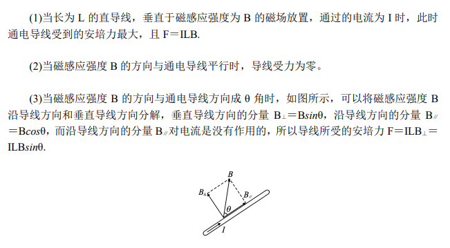
3. Magnitude of Ampere’s Rule (Key Point)

Compilation of Electromagnetic Knowledge for High School Students

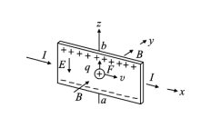
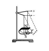
4. The Effect of Uniform Magnetic Field on Current-Carrying Coil

The magnetic field exerts a torque on the current-carrying coil. The Ampere’s torque exerted on the current-carrying coil (current I, area S) in a magnetic field (magnetic induction intensity B) ranges from 0 to IBS. When the magnetic field direction is parallel to the coil, the torque reaches its maximum value IBS; when perpendicular, MB=0.
To determine the direction of the torque, first use the left-hand rule to determine the direction of the Ampere’s force on each side of the coil.
The torque exerted by the magnetic field on the current-carrying coil has the following characteristics: it is independent of the shape of the coil; it is independent of the position of the axis of rotation.

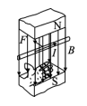
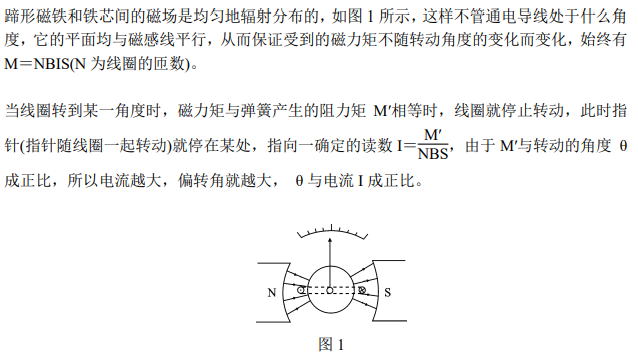
5. Electromagnetic Galvanometer

(1) Purpose
To measure the magnitude and direction of current.
(2) The construction of the electromagnetic galvanometer mainly includes: horseshoe magnet, cylindrical iron core, coil, spiral spring, pointer, and scale.
(3) Principle
Compilation of Electromagnetic Knowledge for High School Students

2. Lorentz Force

1. Magnitude and Direction of Lorentz Force

(1) Lorentz Force
The force exerted by the magnetic field on a moving charge is called the Lorentz force.
(2) Direction of Lorentz Force
① Determination Method—Left-Hand Rule: Spread your left hand, making your thumb perpendicular to the other four fingers, all within the same plane; let the magnetic field lines enter your palm and direct your four fingers towards the direction of the positive charge’s motion. The direction indicated by your thumb is the direction of the Lorentz force on the moving positive charge in the magnetic field.
② Direction Characteristics: F⊥B, F⊥v, meaning F is perpendicular to the plane defined by B and v.
(3) Magnitude of Lorentz Force
Calculation formula: F=qvBsin θ, where q is the charge of the particle, v is the particle’s velocity, B is the strength of the magnetic field, and θ is the angle between the particle’s velocity direction and the magnetic induction direction.
① If the charged particle’s motion direction is perpendicular to the magnetic induction direction, then F=qvB.
② If the charged particle’s motion direction is parallel to the magnetic induction direction, then F=0.
③ If the charged particle is stationary in the magnetic field, then F=0.

3. Motion and Application of Charged Particles in Magnetic Fields

1. Motion of Charged Particles in a Uniform Magnetic Field

Compilation of Electromagnetic Knowledge for High School Students

2. Television Picture Tube

Compilation of Electromagnetic Knowledge for High School Students

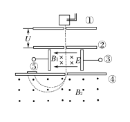
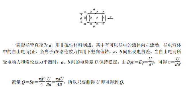
3. Velocity Selector (Key Point)

(1) Purpose
To select charged particles with specific speed using mutually perpendicular electric and magnetic fields.
(2) Basic Structure
As shown in the figure, a uniform electric field E is generated between two parallel metal plates, and the direction of the uniform magnetic field is perpendicular to the direction of the uniform electric field.
(3) Principle
Compilation of Electromagnetic Knowledge for High School Students
(4) Characteristics:
① The velocity selector only selects the speed (magnitude and direction) of the particle, not its mass or charge; as shown in the figure, if it enters from the right side, it cannot pass through the field area.
Compilation of Electromagnetic Knowledge for High School Students
② The sizes and directions of the three physical quantities B, E, and v in the velocity selector are mutually constrained, ensuring that the electric force and Lorentz force on the particle are equal and opposite; changing only the direction of the magnetic field B will cause the particle to deviate.

4. Mass Spectrometer (Key Point)

(1) Purpose
To analyze the isotopes of various elements and measure their mass and percentage content.
(2) Structure
As shown in the figure, mainly composed of the following parts:
Compilation of Electromagnetic Knowledge for High School Students
① Charged particle injector; ② Acceleration electric field (U); ③ Velocity selector (B1, E); ④ Deflection magnetic field (B2); ⑤ Photographic plate.
(3) Principle
Compilation of Electromagnetic Knowledge for High School Students

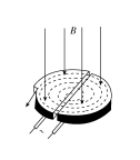
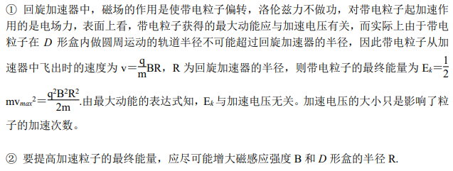
5. Cyclotron (Key Point)

(1) Composition
Compilation of Electromagnetic Knowledge for High School Students
It consists of two D-shaped boxes, a large electromagnet, and a high-frequency oscillating alternating voltage; a voltage U can be formed between the D-shaped boxes.
(2) Principle
It uses the accelerating effect of the electric field on charged particles and the deflecting effect of the magnetic field on moving charges to obtain high-energy particles.
① The magnetic field’s effect: Charged particles entering the uniform magnetic field at a certain speed, perpendicular to the direction of the magnetic field, perform uniform circular motion under the action of Lorentz force, where the period is independent of speed and radius, allowing charged particles to enter the D-shaped box for equal time (half a period) and then enter the electric field for acceleration.
[Note] The uniform magnetic field added to the cyclotron should be perpendicular to the face of the D-shaped box.
② Electric field effect: The narrow gap area between the two D-shaped boxes has a periodically varying uniform electric field perpendicular to the cross-section of the two D-shaped boxes; charged particles are accelerated when passing through this area. The acceleration time of the charged particles in the electric field can be neglected, as the gap between the two D-shaped boxes is small, and the acceleration effect depends on the acceleration voltage, independent of the gap width.
③ Alternating voltage: To ensure that each time charged particles pass through the gap they are accelerated, the alternating voltage with a frequency equal to the particle’s motion period should be applied at the gap.
(3) Maximum kinetic energy gained by charged particles
Compilation of Electromagnetic Knowledge for High School Students

6. Technological Applications of Charged Particles in Magnetic Fields

(1) Hall Effect
① Definition:
Compilation of Electromagnetic Knowledge for High School Students
As shown in the figure, when a current-carrying conductor with a rectangular cross-section is placed in a uniform magnetic field, a potential difference appears in the direction perpendicular to both the magnetic field and the current direction, which is called the Hall effect.
② Principle: The directed moving charges in the conductor are deflected by the Lorentz force in the magnetic field, resulting in the accumulation of different charges on the top and bottom of the conductor, creating a potential difference.
③ Related Concepts: The potential difference generated in the Hall effect is called Hall potential difference or Hall voltage. Hall voltage is related to the current, magnetic induction intensity, and the thickness of the rectangular conductor. The components made using the Hall effect are called Hall elements. Hall elements are an important magnetic sensor.
(2) Electromagnetic Flow Meter
Compilation of Electromagnetic Knowledge for High School Students

Leave a Comment