RS485 communication is a commonly used communication method in the industry, widely applied with a simple circuit. Below is a circuit diagram of the 485 interface:
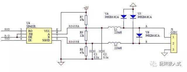
This image is one I found online; it is a commonly used circuit. Although many people use it this way and I haven’t heard of any issues, I believe there is a problem with this circuit, specifically with the three TVS diodes.
The TVS diodes in the diagram are rated at 6.8V, which I believe is inappropriate. In my circuit, I use 13V because, from the RS485 level conversion chip, I found:
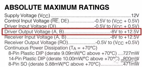
The Differential Driver Output is a maximum of 5V under load conditions, but the Driver Output Voltage can reach a maximum of 12.5V. Therefore, when selecting TVS diodes, I always choose 13V.
 Statement: This article is authorized to be transferred from “Playing with Embedded Systems,” and the copyright belongs to the author. If there is any infringement, please contact us for deletion!
👇Click Follow, Technical Content Delivered on Time!👇

-
The Tragedy of R&D Personnel—“Ponzi Scheme”
-
Detailed Explanation of Power MOSFET (53-page PPT)
-
How to Become a Senior Embedded Hardware Engineer?
-
A seemingly simple optocoupler circuit, when you understand it from another perspective~~
-
Power Supply Soft Start Principle
-
Very Detailed Basic Knowledge of RF
-
Several Tips for Learning Inductor Saturation, Have You Mastered Them?
-
Circuit Principle of Lithium Battery Protection Board
-
Differences Between STM32, GD32, and ESP32