If you are an industrial control engineer and often deal with communications, you will inevitably encounter the issue of poor driving capability of passive RS232 to RS485 converters.
Previously, I worked on a product in a small company, which was a wireless collector customized for a client who only needed an RS232 interface. After launching it in the market, it ran for three years, with over 100,000 units shipped and basically no feedback on issues. Later, the client wanted to expand to other devices, but the device did not have an RS232 interface. After the engineering department recommended a certain RS232 to RS485 device, we found that the original plan to connect 10 devices on the RS485 bus could only support 4. We thought it was due to the client purchasing a counterfeit converter, so we recommended a branded converter, but the problem persisted, indicating that the cause had not been found, and the client urgently needed a solution.
Cause Analysis:
Since the number of devices that can be connected is reduced, it is certainly due to insufficient driving capability. Therefore, we immediately thought of disassembling this passive RS485 converter to understand its internal design principles. We bought five types of converters from the market, including both counterfeit and branded ones. After disassembling them, we quickly drew the schematic due to the simple internal structure. The term ‘passive’ means that no external power supply is required, but there still needs to be a source of power, mainly how to siphon power. After analysis, there are mainly two schemes:
As shown in Figure 1, the RTS, CTS, and DSR pins (pin 6, 7, 8) of the DB9 port are generally not needed during the conversion from RS232 to RS485. Most computers adhere to the RS232-C standard and use the DB9 standard interface. Therefore, when converting RS232 to RS485, this siphoning method is feasible. However, users must note that the voltage range of the RTS, CTS, and DSR pins is -15V to 15V. When these pins are in an inactive state, the level is -15V, and the upper computer must configure these pins to be active, i.e., at a positive level, to supply power to the module.
Advantages:
Power siphoning from DB9 requires no additional power supply.
Disadvantages:
1. The serial port must be initialized to ensure that the RTS, CTS, and DSR pins are configured to active states to output a positive level, ensuring the level exceeds 7V;
2. Some MCUs without these three pins cannot use this scheme.

▲ Figure 1: Using RTS, CTS, DSR Power Siphoning Scheme
The first power siphoning method can only use positive power and requires serial port initialization. However, in many cases, the RTS, CTS, and DSR signals are not used, and it is unrealistic to require them to constantly output a positive level. Therefore, a second power siphoning method has emerged in the market. The principle of siphoning power mainly consists of two major modules: the first module is a negative pressure charge pump module, responsible for converting negative pressure into positive voltage; the second module is a step-down module, responsible for stabilizing the boosted level at 3.3V (or 5V). The four signal pins RTS, CTS, DSR, and TX can all supply power to the module, overcoming the disadvantages of the first scheme that it cannot use negative pressure, must initialize the serial port, and requires RTS, CTS, DSR.
Advantages:
Can accept both positive and negative pressures, requires no serial port initialization, and any one of RTS, CTS, DSR, or TX can supply power.
Disadvantages:
The boost module is relatively complex, and when powered solely by the TX signal, there may be insufficient power.
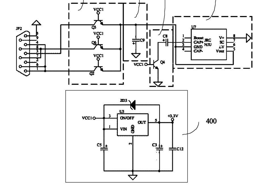
▲ Figure 2: Using RTS, CTS, DSR, TX Power Siphoning Scheme
Solution:
Since the poor load capacity is due to insufficient power supply, we can directly change the power supply scheme. Therefore, we chose an active RS485 converter, where the internal power supply of the module is genuinely sourced from an external terminal rather than siphoned from the signal line. As shown in Figure 4, the external terminal connects to a 3.3~10V power supply, which, after passing through a voltage regulation module, supplies power to the RS485 side and the isolated power supply, with the isolated power supply outputting to the RS232 side. This ensures the entire device receives proper power.
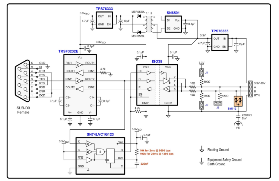
▲ Figure 3: Internal Scheme Disassembly of Active RS485 Converter Module
After changing the scheme, during trial use at the client’s site, it was possible to connect up to 20 RS485 devices (the client’s wiring was a bit long), and it has been running for six months with basically no fault feedback.
From a technical difficulty perspective, passive RS485 is more challenging than active RS485 because the DB9 standard specification does not include a power pin. Passive RS485 needs to siphon power from the RTS, CTS, DSR, and TX pins, and RS232 levels have both positive and negative voltages, requiring negative voltage conversion to positive voltage. Most non-PC controllers do not output RTS, CTS, DSR signals, and relying solely on the TX signal for power may lead to insufficient power supply. Additionally, passive RS485, being positioned as a low-end product, generally lacks robust product protection measures such as overcurrent, overvoltage, lightning, ESD protection, and isolation, merely being functional. In contrast, active RS485, due to its higher budget, offers substantial improvements and has put significant effort into protective measures. If using a PC to control downstream RS485 devices or for single, close-range, low-speed applications, one might consider using passive RS485. However, for industrial control sites, data collection, and other high-reliability, high-protection requirements, active RS485 converter modules are the best choice.
Complete Question Bank for Electrical Engineering Beginner Exam 2021 (Includes Answers)
Troubleshooting Inverter Issues? Just One Click!
Have you not owned this amazing tool to review all electrical exam questions?
Which of the five major electrical drawing software (CAD, Eplan, CADe_simu…) do you choose?
Latest Electrical Version CAD Drawing Software with Detailed Installation Guide!
Latest Electrical Drawing Software EPLAN with Detailed Installation Guide!
Common Issues for Beginners Using S7-200 SMART Programming Software (Includes Download Links)
Comprehensive Electrical Calculation EXCEL Sheets, Automatically Generated! No More Seeking Help for Electrical Calculations!
Bluetooth Headphones, Electrical/PLC Introductory Books Available as Gifts? Come Get Your Electrical Gifts!
Basic Skills in PLC Programming: Ladder Diagrams and Control Circuits (Includes 1164 Practical Cases for Mitsubishi PLC)
Still Can’t Understand Electrical Diagrams? Grab the Basics of Electrical Diagram Recognition and Simulation Software, Quickly Get Started with Theory and Practice!
12 Free Electrical Video Courses, 10GB Software/E-books, 30 Days of Free Live Electrical Courses!