The RS485 bus has advantages such as simple structure, long communication distance, fast communication speed, and low cost.
It is widely used in industrial communication, power monitoring, instrumentation, and other industries.
Due to the harsh industrial control environment, more interference coupling can occur in communication lines, affecting the reliability of the RS485 bus, and even damaging the RS485 transceiver chip.
Pulse group interference is a common type of interference. Typically, electrical fast transient (EFT) immunity tests are used to simulate interference and verify the system’s reliability.
1. Sources of Pulse Group Interference
In industrial control environments, instantaneous interference often occurs due to lightning, short circuits, and switching actions with inductive loads. These interferences are short bursts of high-energy pulse disturbances, characterized by groups of pulses, short rise times, and high repetition frequencies.
These disturbances couple onto the RS485 bus. Since these pulses are not single pulses but a series of pulses, they accumulate on the RS485 bus, causing the voltage amplitude of the disturbance to exceed the noise tolerance of the RS485 transceiver, leading to communication errors.
Moreover, since the period of these pulse disturbances is short, the interval between the occurrence of each pulse is brief. When the first pulse disturbance has not yet dissipated, the second pulse follows closely. For the parasitic capacitance on the RS485 bus and the junction capacitance of the RS485 transceiver, charging starts again before it has fully discharged. Since parasitic capacitance is usually small, even a small amount of energy can reach a high voltage, easily damaging the RS485 transceiver and affecting the reliability of RS485 bus communication.
2. Principles of Pulse Group Interference Generation
The voltage level of the pulse group interference source depends on factors such as the inductance of the load circuit and the speed of load disconnection.
Taking switching actions as an example, when a switch is opened, the distance between the dynamic and static contacts is relatively close. The inductance in the circuit induces a back electromotive force that is sufficient to break down the air gap between the contacts, allowing the circuit to conduct.
However, this discharge process is very brief, generating a leading edge pulse in the nanosecond range with a width of several tens of nanoseconds and a peak voltage of several thousand volts. After this pulse ends,
the circuit begins to repeat the process of generating back electromotive force from the inductive load and discharging through the air gap between the dynamic and static contacts of the switch.
This process continues until the energy stored in the inductive load is sufficiently low that it can no longer generate the aforementioned discharge process.
These disturbances couple onto the RS485 bus, forming significant interference that affects communication reliability.
3. Measures to Improve Immunity to Electrical Fast Transient Pulse Groups
Electrical fast transient pulse group interference is common mode interference that can be suppressed using filtering, absorption, or isolation methods.
RS485 Bus Isolation
The main functions of bus isolation are as follows:
1) Ensuring Equipment and Personal Safety – The Impact of High Voltage
RS485 is used for communication between devices. Often, developers are unaware of what type of equipment their clients are connecting their devices to.
If the other party is using a device that reduces 220V to 12V using a simple resistor-capacitor voltage divider with no isolation from the power grid, testing, debugging, and usage can be very dangerous. If the insulation of high-voltage equipment is damaged, high voltage on the RS485 line can threaten both equipment and personal safety.
2) Avoiding Abnormal Reception at the Remote End – The Impact of Potential Difference
In many practical applications, the communication distance can reach several kilometers, with nodes spaced far apart.
Designers often connect the reference ground of each node directly to the local ground as the return ground for signals, which seems like a normal and reliable practice. However, the ground is not an ideal ‘0’ potential; it is also a conductor and has impedance.
When large currents flow through the ground, there will also be a potential difference across the ground where the current flows.
For example, in Figure 1, due to the distance between A and B, the reference ground is not at 0 potential, and the impedance of the ground line is not zero. Due to the current loop effect, the voltage at point A is Vs, while at point B it becomes Vc + Vs.
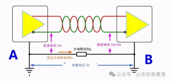
Figure 1. The Impact of Potential Difference
3) Avoiding Data Anomalies and Device Damage – The Impact of Ground Loops
Since there is a potential difference in the ground between nodes, wouldn’t it be sufficient to connect the ground of the two nodes with a single wire?
This is a big mistake! Doing so would only exacerbate the situation; this long wire would form a massive ground loop with the earth! As everyone knows from their school days, a closed loop in a changing magnetic field will generate current.
50Hz AC power lines, large motors, etc., are sources of alternating magnetic fields. If the bus is near or passes through these areas, the ground loop can generate currents of several amperes or even hundreds of amperes.
The common mode voltage generated by the current flowing through the ground loop will affect the normal communication of the bus. In addition to stable magnetic field sources, transient disturbances such as surges from power lines, lightning strikes, and high-frequency noise can also be picked up by this giant ‘loop antenna’, causing communication anomalies.
Adding Ferrite Beads to Absorb Interference
Adding ferrite beads at the device’s entry point can effectively absorb interference. Increasing the number of turns of the communication line through the ferrite bead can enhance the interference absorption effect.
As shown in Figure 2, ferrite beads are added near the RS-485 interface of the device under test.
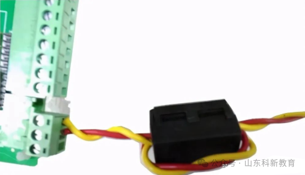
Figure 2. Adding Ferrite Beads to Communication Lines
Using Shielded Twisted Pair Cables
As shown in the figures, in practical applications, RS485 communication lines can use shielded twisted pair cables, with the shielding layer grounded at a single point to effectively suppress electrical fast transient pulse group interference coupling onto the communication line.
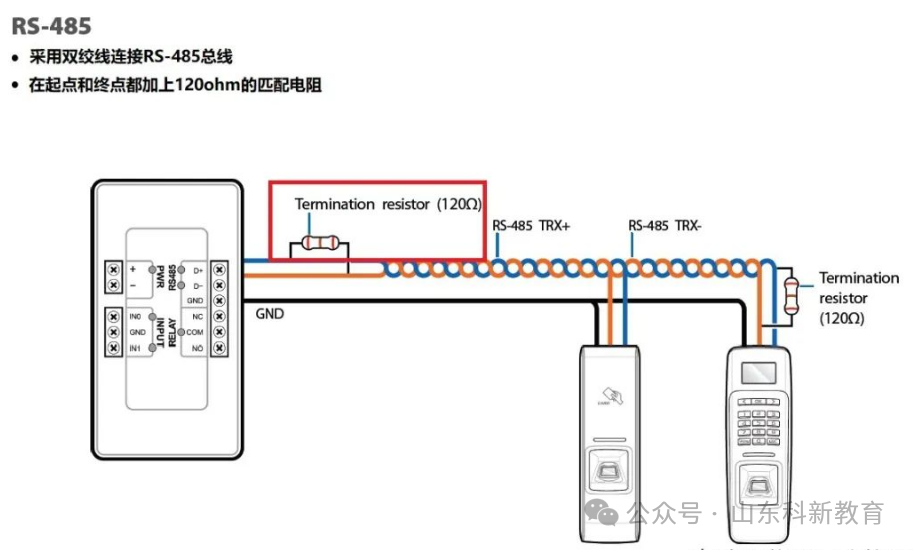
Figure 3. Using Shielded Twisted Pair Cables
Adding Ground TVS to the RS-485 Bus
When adding TVS diodes between A to ground and B to ground, if the voltage amplitude of the electrical fast transient pulse group interference coupled onto the RS485 bus is high, the interference voltage will be clamped by the TVS, protecting the RS485 transceiver.
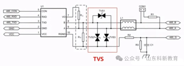
Adding TVS for Overvoltage Protection
RS-485 Bus Series Ferrite Beads
Since ferrite beads behave like resistors at high frequencies, they convert high-frequency energy into heat and dissipate it.
Therefore, placing ferrite beads in series on the RS485 bus will consume the energy of the electrical fast transient pulse group interference when it couples onto the RS485 bus, enhancing the RS485 bus’s immunity to interference.
Source: This article is reprinted from the internet, and the copyright belongs to the original author. If there are copyright issues, please contact us for timely deletion. Thank you!

Scan to Follow
WeChat ID|13615417996
Follow the QR code on the left to get
【Siemens Data Collection】