In engineering, the RS485 control line is often mentioned. What exactly is it? Today, I will discuss the applications related to RS485. By understanding RS485 in depth, you will find that there is indeed a lot of knowledge within it. We will choose some common issues considered in weak electricity for everyone’s understanding.

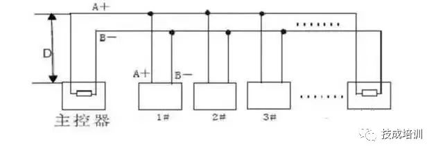
In industrial sites, it is often necessary to collect multi-point data, analog signals, or switch signals, which generally utilize the RS485 bus. RS-485 operates in half-duplex mode and supports multi-point data communication. The RS-485 bus network topology generally adopts a terminal-matching bus structure. That is, a single bus connects each node in series and does not support ring or star networks.
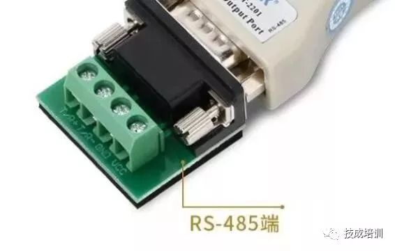
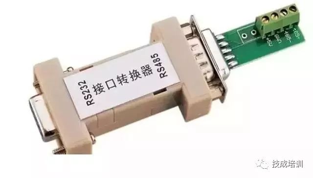
RS485 does not have a specific physical shape, and the interface is chosen based on the actual conditions of the project. RS485 uses differential signaling with negative logic, where +2V to +6V represents ‘0’, and -6V to -2V represents ‘1’.
RS485 has two wiring methods: two-wire and four-wire. The four-wire method can only achieve point-to-point communication and is rarely used now. The two-wire wiring method is commonly used, allowing up to 32 nodes to be connected on the same bus topology.
The communication distance of the 485 bus can reach up to 1200 meters. According to the theoretical structure of the 485 bus, under ideal conditions, the transmission distance can reach 1200 meters. The conditions are that the communication cable is of high quality, the baud rate is 9600, and only one 485 device is loaded to achieve this distance. Therefore, the actual stable communication distance of the 485 bus often does not reach 1200 meters. If there are multiple 485 devices loaded, if the cable impedance does not meet standards, if the wire gauge is too thin, if the converter quality is poor, if the device’s lightning protection is complex, and if the baud rate increases, these factors will all reduce the communication distance.

In general situations, ordinary twisted pair cables can be used. In environments with higher requirements, shielded coaxial cables can be used. When using RS485 interfaces, the maximum cable length allowed for data signal transmission from the RS485 interface to the load is inversely proportional to the baud rate of signal transmission. This length data is mainly affected by signal distortion and noise.
Theoretically, the maximum transmission distance of RS485 can reach 1200 meters, but in practical applications, the transmission distance is shorter than 1200 meters, depending on the surrounding environment. During transmission, repeaters can be used to amplify the signal, allowing for up to eight repeaters, meaning that theoretically, the maximum transmission distance of RS485 can reach 9.6 kilometers. If long-distance transmission is truly needed, fiber optics can be used as the transmission medium, with a photoelectric converter added at both ends. The transmission distance of multi-mode fiber is 5-10 kilometers, while single-mode fiber can reach up to 50 kilometers.

1. What type of communication line should be used for the 485 bus? How many devices can be connected on one bus?
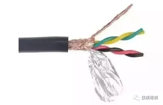
It is essential to use RVSP shielded twisted pair cables. The specifications of the shielded twisted pair cable used depend on the distance of the 485 communication line and the number of devices connected, as shown in the table below. Using shielded twisted pair helps reduce and eliminate the distributed capacitance generated between the two 485 communication lines and the common mode interference from the surrounding communication lines.
Some say that the 485 bus can communicate with 128 devices.
However, not all 485 converters can support 128 devices; it depends on the model of the chip in the 485 converter and the chip model of the 485 device. The load capacity can only be determined according to the lower specifications of the chips. Generally, the load capacity of 485 chips has three levels – 32 devices, 128 devices, and 256 devices. Moreover, the nominal value is often not achievable in practice. The longer the communication distance, the higher the baud rate, the thinner the wire gauge, the poorer the wire quality, the worse the converter quality, and the stronger the lightning protection, all these factors will reduce the actual load capacity.
Most engineers are accustomed to using category 5 or category 5e network cables as the 485 communication line, which is incorrect. This is because:
(1) Ordinary network cables do not have shielding and cannot prevent common mode interference.
(2) Cables with too thin a gauge cannot be used, as this will reduce transmission distance and the number of devices that can be connected, at least 0.4mm² or standard network cables should be used.
(3) Network cables are made of solid copper wire, which is more prone to breakage compared to multi-core wires.
2. Why is grounding necessary?
The 485 transceiver can only operate normally when the common mode voltage is between -7V to +12V. If it exceeds this range, it will affect communication and may severely damage the communication interface. Common mode interference will increase the above common mode voltage. One effective means to eliminate common mode interference is to use the shielding layer of the 485 communication line as the ground, connecting the equipment, computers, and other devices in the network together and reliably grounding them.
3. How should the 485 communication line be routed?
The communication line should be kept as far away as possible from high-voltage lines, fluorescent lights, and other sources of interference. If the communication line cannot be kept away from power lines and other sources of interference, it should be perpendicular to the power lines and not parallel, and definitely not bundled together, using high-quality twisted pair cables for routing.
4. Why should the 485 bus use a daisy chain structure instead of a star structure?
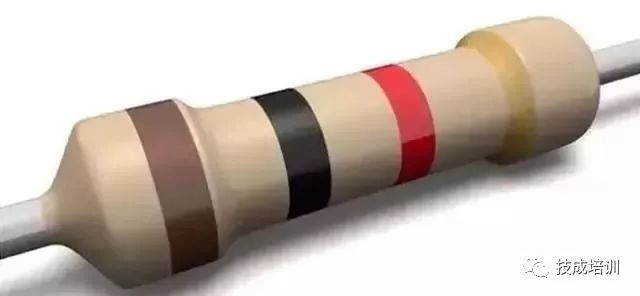
The star structure can cause reflected signals, which can affect 485 communication. The branch lines from the bus to each terminal device should be kept as short as possible, generally not exceeding 5 meters. If the branch lines are not terminated, there will be reflected signals that can strongly interfere with communication, and they should be removed. It is best to attach 120Ω terminal resistors at both ends of the RS485 devices.
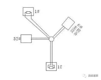
Star connection as shown:
5. Can there be junctions between devices on the 485 bus?
In the same network system, using the same type of cable, it is advisable to minimize junctions in the line. Ensure that the junctions are well soldered, tightly wrapped, and avoid loosening and oxidation. Ensure a single, continuous signal path as the bus.
6. What are common mode interference and differential mode interference? How to eliminate interference on communication lines?
The 485 communication line consists of two twisted wires, and it transmits signals through the voltage difference between the two communication lines, hence called differential voltage transmission. Differential mode interference occurs between the two signal lines and is a symmetric interference. The method to eliminate differential mode interference is to add a bias resistor (matching resistor in the ball machine) in the circuit and use twisted pairs; common mode interference occurs between the signal line and ground and is asymmetric interference. Methods to eliminate common mode interference include:
(1) Using shielded twisted pair cables and ensuring effective grounding.
(2) In strong electric fields, consider using galvanized pipe shielding.
(3) During wiring, keep away from high-voltage lines and do not bundle high-voltage power lines with signal lines.
(4) Use linear regulated power supplies or high-quality switching power supplies (ripple interference less than 50mV).
7. Under what circumstances should terminal resistors be added on the 485 bus?
Generally, terminal resistors are not required. However, if the 485 communication distance exceeds 300 meters, terminal resistors should be added at the start and end of the 485 communication. Especially when there are fewer devices on the 485 bus. When there are many devices (e.g., more than 22), terminal resistors are generally not needed, as they will reduce the load capacity of the 485 bus. The connection method for the 120Ω matching resistor at the ball machine terminal is as follows: the 120Ω matching resistor can be connected by toggling the DIP switch on the chassis of the ball machine. The 120Ω matching resistor is set to not be connected by default when the machine is delivered. You can connect it by switching the 10th position of the DIP switch to ON. Conversely, if you do not connect the 120Ω matching resistor, set the 10th position to OFF.
8. Issues in Practical Applications
In practical construction, users often adopt a star connection method. In this case, terminal resistors must be connected to the two devices furthest apart on the line (as shown in the figure, devices 1# and 15#). However, since this connection method does not meet the usage requirements of the RS485 industrial standard, it can easily cause signal reflection, reduced anti-interference ability, and other issues, leading to decreased reliability of control signals. The phenomena observed include the ball machine being completely uncontrollable or running automatically without stopping.
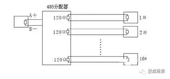
For such cases, it is recommended to use an RS485 distributor. This product can effectively convert the star connection into a connection method that complies with RS485 industrial standards, thus avoiding problems and improving communication reliability, as shown in the figure below.
9. Recommended Cables for Maximum Transmission Distance without Repeaters
1) Ordinary twisted shielded cable STP-120Ω (for RS485 & CAN) one pair 20 AWG, with an outer diameter of approximately 7.7mm. Suitable for indoor, pipeline, and general industrial environments. When using, the shielding layer should be grounded at one end!
(2) Ordinary twisted shielded cable STP-120Ω (for RS485 & CAN) one pair 18 AWG, with an outer diameter of approximately 8.2mm. Suitable for indoor, pipeline, and general industrial environments. When using, the shielding layer should be grounded at one end!
(3) Armored twisted shielded cable ASTP-120Ω (for RS485 & CAN) one pair 18 AWG, with an outer diameter of approximately 12.3mm. Suitable for environments with severe interference, frequent rodent damage, and where lightning and explosion protection is required. When using, it is recommended to ground the armored layer at both ends and the innermost shielding at one end.

1. How to prevent faults from occurring?
To reduce communication faults, the following suggestions are proposed.
(1) It is recommended that users use and purchase the 485 converters provided by the manufacturer or 485 converters from brands recommended by the manufacturer.
(2) The manufacturer will conduct extensive testing on the 485 converters that are compatible with their products and will require the manufacturers of the 485 converters to produce and quality test according to fixed performance parameters, so they have better compatibility with access control devices. Do not be tempted to buy cheap, unbranded 485 converters.
(3) Strictly follow the construction specifications for the 485 bus to eliminate any fluke mentality.
(4) For long lines with many loads, adopt scientific and reserved solutions.
(5) If the communication distance is too long, such as exceeding 500 meters, it is recommended to use repeaters or a 485 HUB to solve the problem.
(6) If there are too many loads, such as more than 30 devices on one bus, it is recommended to use a 485 HUB to solve the problem.
(7) Bring all debugging equipment for on-site debugging. During on-site debugging, be sure to carry several converters that can connect long distances and multiple loads, a commonly used laptop, a multimeter for testing circuit breaks, and several 120-ohm terminal resistors.
2. What are the common communication faults when using the 485 bus structure?
(1) No communication, no response.
(2) Data can be uploaded, but not downloaded.
(3) During communication, the system indicates interference, or the communication indicator keeps flashing even when not communicating.
(4) Sometimes communication works, sometimes it does not; some commands can go through while others cannot.
3. What debugging methods are available when a fault occurs?
Before debugging, ensure that the device wiring is correct and that the construction meets specifications. Depending on the encountered problems, the following debugging methods can be employed.
(1) Common Ground Method:
Use one line or shielded wire to connect the GND ground of all 485 devices together, which can avoid potential differences affecting communication between all devices.
(2) Terminal Resistor Method:
Connect a 120-ohm terminal resistor in parallel on the last 485 device’s 485+ and 485- to improve communication quality.
(3) Intermediate Section Disconnection Method:
Check if there are too many devices loaded, if the communication distance is too long, or if a specific device is affecting the entire communication line by disconnecting from the middle.
(4) Single Pull Line Method:
Independently pull a simple line to the device to check if the wiring is causing the communication fault.
(5) Converter Replacement Method:
Carry several converters to rule out whether the quality of the converter is affecting communication quality.
(6) Laptop Debugging Method:
Ensure that the laptop you carry is a functioning communication device, and use it to replace the client’s computer for communication. If it works, it indicates that the client’s computer’s serial port may be damaged or malfunctioning.
In weak current intelligent engineering, the application of RS485 is widespread, most commonly used in access control systems, building automation systems, intelligent lighting systems, parking management systems, etc. As digital networks continue to become more widespread, the use of RS485 in weak current applications is decreasing.
Disclaimer: This article is reproduced from the internet, and the copyright belongs to the original author. If there are copyright issues, please contact us in time to delete it. Thank you!
2023 Electrician Beginner Exam Question Bank Full Version (with Answers)
Three essential tools for electricians, easily accessible with WeChat!
[Collection] The “Path” for Ten-Year-Old Electricians, Secrets to Earning Over 10,000 a Month!
Five Major Electrical Drawing Software (CAD, Eplan, CADe_simu…), which one do you choose?
The latest electrical CAD drawing software, with a super detailed installation tutorial!
The latest electrical drawing software EPLAN, with a super detailed installation tutorial!
Common Problems for Beginners Using S7-200 SMART Programming Software (with Download Link)
Comprehensive Electrical Calculation EXCEL Sheets, Automatically Generate! No More Asking for Electrical Calculations!
Bluetooth Headphones, Introductory Books for Electricians/PLC are available! Come and claim your electrical gifts!
PLC Programming Basics: Ladder Diagrams and Control Circuits (with 1164 Practical Cases for Mitsubishi PLC)
Still can’t understand electrical diagrams? Basics of Electrical Diagram Recognition and Simulation Software available, quickly get started!
12 Free Electrician Video Courses, 10GB Software/E-books, and 30 Days of Free Electrician Live Classes are being given away!