When the CAN bus malfunctions or data transmission is abnormal, various strange fault phenomena often occur, such as abnormal dashboard displays, inability to start the vehicle, failure to turn off after starting, decreased vehicle performance, and loss of certain electronic control system functions. This is because relevant data or information is transmitted through the CAN bus, and if the transmission fails, multiple associated faults can arise, potentially causing the entire network system to collapse. The most common fault symptom is the abnormal display on the dashboard.
During the repair process, the specific fault symptoms should first be checked. Based on the fault symptoms and network structure diagram, a preliminary analysis of possible causes should be conducted, followed by the use of relevant diagnostic instruments for diagnosis. Based on the diagnostic results, relevant repair plans should be formulated, ensuring clarity of purpose and goals.
Next, identify the specific fault location and cause, while using appropriate testing methods and measurement results to locate the fault point, thereby thoroughly eliminating the fault.
This issue introduces the “Voltage Measurement Method for CAN Bus”.
Since the CAN network uses multiple protocols, each control module’s port has a standard voltage under normal conditions. Therefore, the voltage measurement method can be used to determine if there are issues such as ground or power short circuits, or short circuits between phase lines.
To determine whether the CAN H or CAN L wire is damaged or if the signal is normal, its ground voltage (average voltage) can be measured. The measurement point is usually at the OBD diagnostic interface, as shown in the figure below.
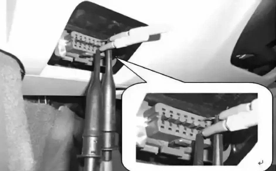
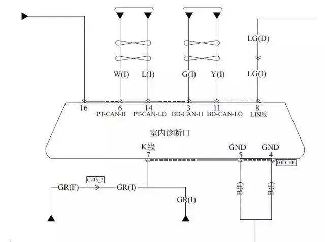
The 6th pin of the diagnostic interface connects to the CAN H wire, and the 14th pin connects to the CAN L wire. If two sets of CAN bus are connected to the diagnostic interface, the power CAN bus uses the 6th and 14th pins, while the comfort bus uses the 3rd and 11th pins. The meanings of the diagnostic interface pins are shown in the figure below.
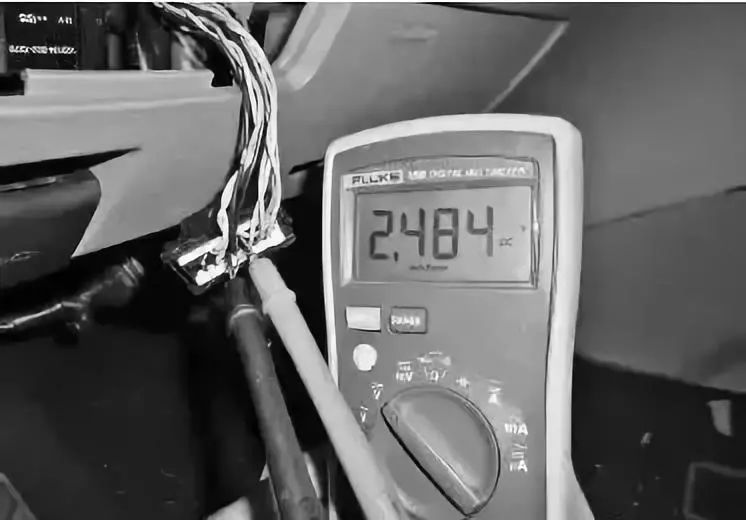
Under normal circumstances, when the CAN bus is awakened, the ground voltage of CAN H is about 2.656V, and the ground voltage of CAN L is about 2.319V, with their sum being 4.975V ▼
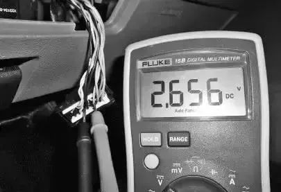
Normal CAN H Voltage
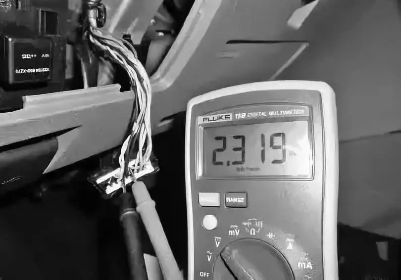
Normal CAN L Voltage
Common causes of CAN faults include short circuits in the CAN wire, short circuits to the power supply, short circuits to ground, and reversed connections.
1. Short Circuit Between CAN H and CAN L
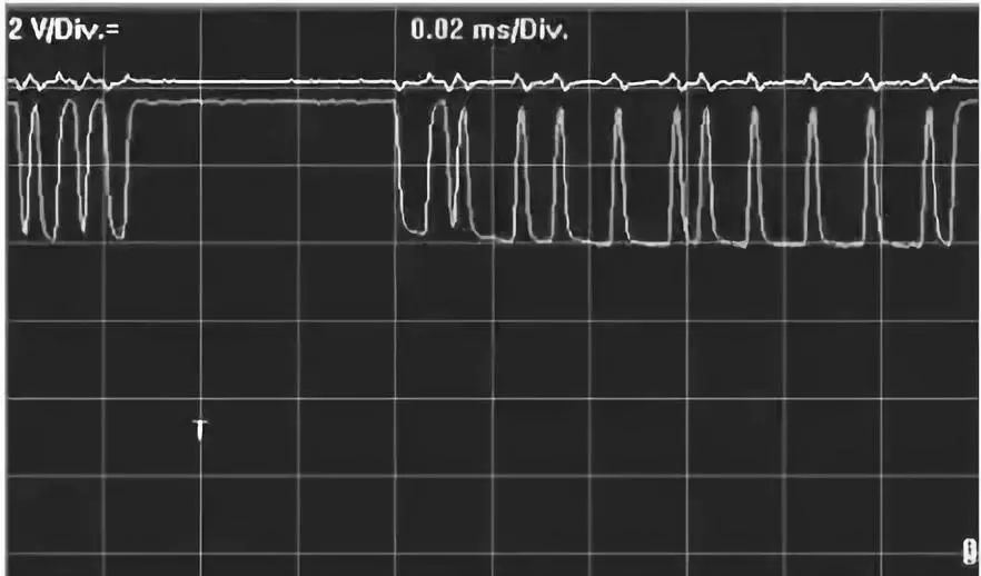
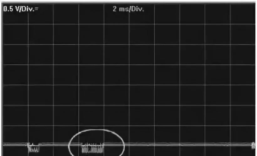
When there is a short circuit between CAN H and CAN L, the CAN network will shut down, and communication will no longer be possible. Corresponding network fault codes will be present. The bus waveform of the short circuit between CAN H and CAN L is shown in the figure below.
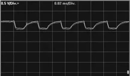
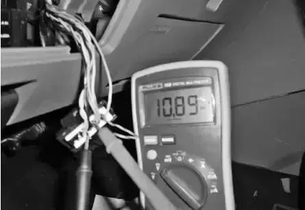
After the two are short-circuited, the CAN voltage level is at a latent voltage value (about 2.5V). Actual measurements of the voltage of the two CAN wires will show that it remains around 2.5V and does not change significantly, as shown below.
Fault elimination method: By plugging and unplugging the control modules (nodes) on the CAN bus, it can be determined if the short circuit is caused by a node or by a wire connection.
Disconnect each node one by one; if the voltage returns to normal, it indicates that the node has a problem. If the voltage does not change after disconnecting all nodes, it indicates a wire short circuit.
2. Short Circuit of CAN H to Power (Positive Terminal)
When a short circuit occurs between CAN H and the power supply (positive terminal), due to the fault tolerance characteristics of the CAN bus, the entire CAN network may be unable to communicate or generate related fault codes.
Taking a short circuit to a 12V power supply as an example, at this time, the voltage level of CAN H is set to 12V, and the latent voltage of the CAN L wire is set to approximately 12V. The bus waveform of the short circuit of CAN H to the power supply is shown in the figure below.
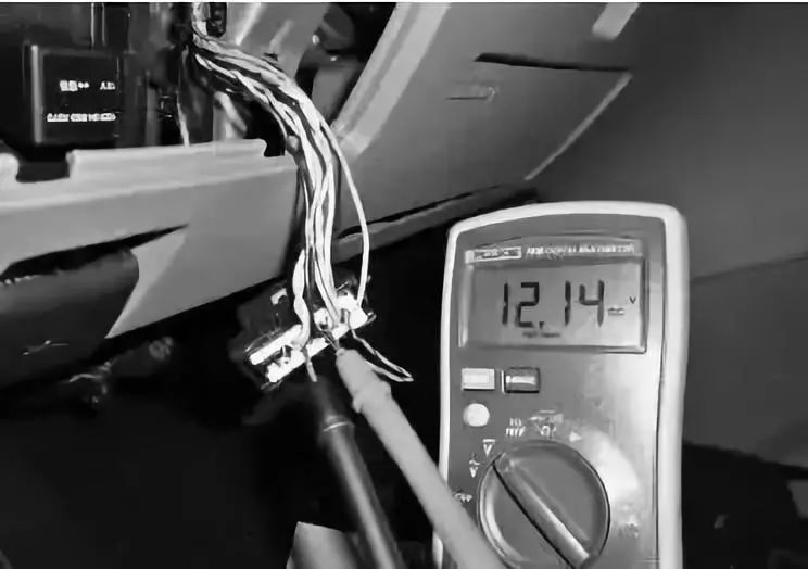
When measuring the voltage, if the CAN H voltage is 12V and the CAN L voltage is approximately 11V, it indicates that this type of fault has occurred. The CAN H voltage in the short circuit to the power supply is shown in the figure below.
The CAN L voltage in the short circuit of CAN H to the power supply is shown in the figure below..
Fault cause: If the short circuit of the CAN H wire to the external power supply is not the cause, then this fault may be caused by a damaged CAN transceiver within the control module. The fault finding method is the same as above.
3. Short Circuit of CAN H to Ground
When a short circuit occurs between CAN H and ground, due to the fault tolerance characteristics of the CAN bus, the entire CAN network may be unable to communicate or generate related fault codes.
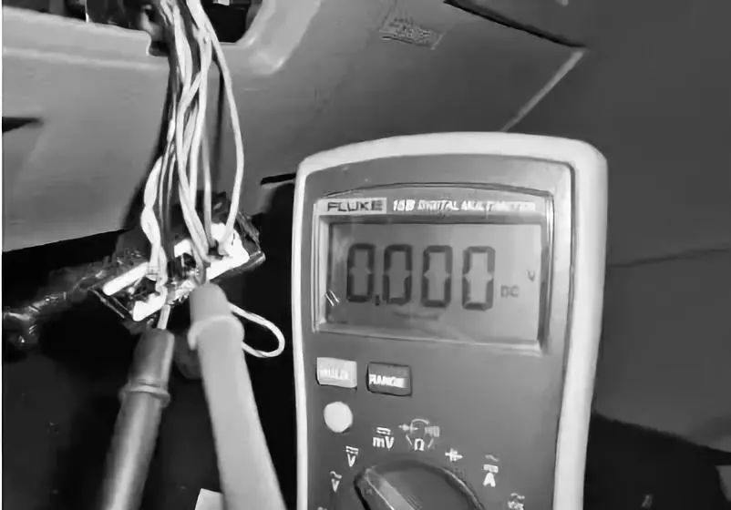
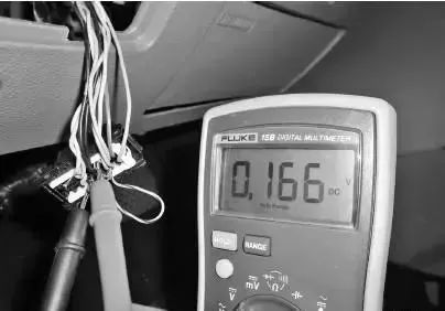
The voltage of CAN H is at 0V, and the voltage of CAN L is also at 0V, but a small amount of voltage variation can still be observed on the CAN L wire. The bus waveform of the short circuit of CAN H to ground is shown in the figure below.
When measuring the voltage, if both CAN H and CAN L voltages are approximately 0V, and there are no open circuit issues, it indicates that this type of fault has occurred. The CAN H voltage in the short circuit to ground is shown in the figure below.
The CAN L voltage in the short circuit of CAN H to ground is shown in the figure below.
Fault cause: If the short circuit of the CAN H wire to the external ground is not the cause, then this fault may be caused by a damaged CAN transceiver within the control module. The fault finding method is the same as above.
Source: Electrical Control Knowledge Transporter