1. Introduction
USB, as a new interconnection protocol for PCs, makes the connection between peripherals and computers more efficient and convenient. This interface is suitable for various devices, not only featuring fast speed, plug-and-play, and support for hot-swapping, but also allowing up to 127 devices to connect simultaneously, solving issues such as resource conflicts, interrupt requests (IRQs), and direct memory access (DMAs). Therefore, more and more developers want to use this standard interface in their products. RS-232 is a common method for connecting a single device to a computer, with simple hardware implementation, making it widely adopted in traditional devices. General IC card access control attendance systems also use RS-232 interfaces to communicate with PCs. If USB technology is applied to the data communication between IC card access control attendance systems and PCs, it can not only provide the advantages of USB communication for IC card access control attendance devices but also free up one RS-232 serial port for other communications on the PC.
2. Overview of USB System
The USB specification describes the characteristics of the bus, protocol definitions, programming interfaces, and other features required when designing and building systems. USB is a master-slave bus; during operation, the USB host is in master mode, and the device is in slave mode. The only system resources needed for the USB system are the memory space used by the USB system software, the memory address space (I/O address space) used by the USB master controller, and the interrupt request (IRQ) lines. USB devices can be functional devices such as monitors, mice, or hubs. They can operate as low-speed or high-speed devices. Low-speed devices have a maximum rate limited to 1.5 Mb/s, and each device has some proprietary registers, known as endpoints, that can be accessed indirectly through device drivers during data exchange. Each endpoint supports several special transfer types and has a unique address and transfer direction. Notably, endpoint 0 is used only for control transfers and can operate bidirectionally. After the system is powered on, the USB host is responsible for detecting device connections and disconnections, initializing the device enumeration process, and automatically reconfiguring the system after installing device drivers based on the device descriptor table, collecting status information for each device. The device descriptor table identifies the device’s attributes, features, and describes its communication requirements. The USB host configures the device, finds drivers, and communicates with the device based on this information. A typical USB data transfer is initiated by the device driver when it needs to communicate with the device, providing a memory buffer to store data received or about to be sent by the device. The USB driver provides an interface between the USB device driver and the USB master controller, converting transfer requests into USB transactions while adhering to bandwidth requirements and protocol structures. Some transfers consist of large data blocks, requiring them to be divided into several transactions before transmission. Devices with similar functions can form a class, facilitating the sharing of common features and using a common device driver. Each class can define its own descriptors, such as HID class descriptors and report descriptors. The HID class consists of devices that control computer systems by humans; it defines a structure describing HID devices and indicates the communication requirements of the devices. The HID device descriptor must support endpoint input interrupts, and firmware must include a report descriptor indicating the format for receiving and sending data. After introducing an RS-232 to USB interface conversion module into the IC card access control attendance system, it should be classified as an HID device based on the system’s characteristics. Therefore, two special HID class requests must be supported: SetReport and GetReport. These requests enable the device to receive and send general device information to the host. In the absence of an interrupt output endpoint, SetReport is the only way for the host to send data to the HID device.
3. System Requirements
To implement the RS-232-USB interface conversion in the IC card access control attendance system, a USB-capable host is required, along with drivers provided by the operating system for communication with peripherals. Additionally, a client application program must be developed to run on the host. On the device side, a main controller chip with a USB interface is needed, as well as the USB communication code to be executed on the main controller and the relevant code to perform peripheral functions.
1. Host Requirements
The host must be able to receive USB data through the device driver and make this data effective for the application processing these requests. There must be a driver in the host responsible for handling USB transfers, identifying devices, and sending/receiving data to/from USB devices; additionally, a device driver for virtualizing the serial port must emulate a real serial port. This driver must be capable of receiving and sending USB data like a real serial port.
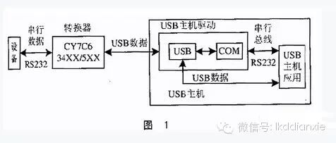
From the application’s perspective, the device driver must be able to send and receive data, either by using a virtualized serial port or by converting to USB data. Microsoft provides a device driver called USB POS, which allows applications to access USB devices as if they were connected to a standard serial port. The overall structure of the system is shown in Figure 1.
2. Device Requirements
When defining the microcontroller to be used, some communication requirements must be specified, such as communication speed, frequency, and the amount of data to be transmitted. Considering the effective communication speed of the IC card access control attendance system, the converter can be used as a low-speed device, with communication speeds ranging from 10 to 100 Kb/s. Considering the amount of data being transmitted and the transmission frequency, this system uses interrupt transfer types, which can occur in two directions but not simultaneously; this type of transfer requires completing a considerable data transmission task within a specified time.
The conversion module can be used for data transmission and reception for PCs, with the operating system providing an HID driver that allows the use of interrupt transfer mode. For a low-speed device transaction, the maximum packet size for interrupt transfer is 8 bytes; if a large amount of data needs to be sent, it must be divided into many transactions.
Another feature to be defined by the conversion module is the required number of endpoints. As mentioned above, endpoints are buffers used by the microcontroller to send and receive data during USB communication. In this system, the converter defines two endpoints: one endpoint (endpoint 0) is used for control transfers, and the other endpoint is an interrupt input endpoint, defined for sending data to the PC.
Based on the above requirements, by researching and comparing existing microcontrollers, considering factors such as memory space, price, and development kits, we chose an 8-bit RISC microcontroller from the Cypress family, CY7C*XX/5XX. It uses a Harvard bus structure and is a low-cost solution for low-speed application devices with higher I/O requirements.
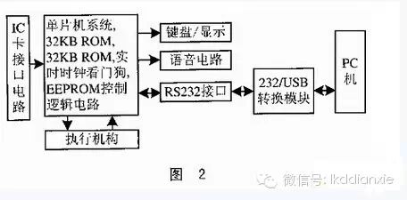
Figure 2 shows the hardware block diagram for USB communication implementation in the IC card access control attendance system.
4. Software Design and Execution
The system software consists of six parts: descriptor definition, device detection and enumeration, endpoint interrupt service routine, USB data exchange module, serial port data exchange module, and USB/Serial module interface. Below is a brief description of the functions and implementation ideas of some of the module programs.
1. Descriptor Definition
A descriptor is a formatted block of data results or information that allows the host to recognize the device. Each descriptor contains information about the entire device or specific elements. All USB peripherals must respond to requests for standard USB descriptors.
This system uses one interface and two endpoints (control and interrupt input). Due to limitations in Win98, interrupt output endpoints cannot be used; therefore, to solve this problem, we use SetReport in endpoint 0 to transfer data from the PC to the IC card access control attendance device.
Data reception is completed in Output Reports. Based on the maximum data amount sent to the IC card access control attendance device, the system defines it as 16K of 8-bit fields. Data sent to the host is completed in Input Reports, consisting of 8K of 8-bit fields.
2. Device Detection and Enumeration
When a USB Human Interface Device (HID) is first connected to the bus, it is powered by the bus but remains non-functional until a bus reset occurs. The pull-up resistor on the D- line notifies the Hub of a new device connection, and the host also becomes aware of the newly connected USB device and resets it. Following the input packet, the host sends a configuration packet, reading the device descriptor from the default address 0. After reading the descriptor, the host assigns a new address to the device and continues to query information about the device descriptor, configuration descriptor, and human report descriptor, allowing the device to begin responding to the newly assigned address. Based on the information returned from the device, the host knows the number of data terminals supported by the device, completing the enumeration process. After enumeration, Windows adds the new device to the Control Panel’s Device Manager for display.
To achieve this, the microcontroller must have code written to access the descriptors, allowing effective identification and response to requests sent by the host during device enumeration. On the device side, an INF file needs to be created to allow Windows to recognize the device and find its driver. Since the operating system provides a simple INF file, only the program written into the microcontroller needs to be developed during the process.
3. Data Sending and Receiving Process
Data is sent to the access control attendance system using SetReport in control endpoint 0. The host first requests the access control attendance system to send data; after the device responds to the request, the host begins execution. When data arrives at the device’s endpoint 0, it generates an interrupt for the device. At this point, the corresponding interrupt service routine will copy the data to the data buffer. Once entering the interrupt service routine for endpoint 0, all interrupts must be disabled to ensure correct data copying.
The microprocessor’s data buffer is programmed to receive 64 bytes, a value stored in the header request information of the setup packet. The maximum packet size received from the host is determined based on the maximum amount of data it will send to the access control attendance system.
The system also uses a Put_command thread to send data to the access control attendance system’s serial port through an I/O port pin. During the execution of this thread, start bits, stop bits, and appropriate delays are inserted according to the serial communication protocol.
The process of receiving data from the access control attendance system is completed using endpoint 1. Endpoint 1 is configured as an interrupt input endpoint; when a start bit arrives at the pin, GPIO interrupts must be enabled, and all other types of interrupts must be disabled. The design uses a Get_Serial thread to collect serial data emitted from the I/O pin and store it in the data buffer. This thread is also responsible for checking the correctness of the received start and stop bits. When 8 bytes are received, the data in the receive buffer is copied to the buffer of endpoint 1, allowing the microprocessor to respond to interrupt input requests.
Considering that the effective baud rate range for a typical serial port is between 300 and 19,200 bps, we consider the maximum baud rate of 19,200 bps. Transmitting one character takes approximately 0.75 ms; an input interrupt sends an 8-byte data packet approximately every 10 ms. Therefore, designing a 128-byte fast data buffer can ensure that no data is lost.
The RS-232-USB interface conversion module is used to improve our IC card access control attendance system, and it works effectively.