01Diagnostic Interface Layout Diagram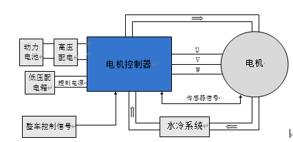
*Electrical Block Diagram of the Drive System
The controller, as a key power component in new energy vehicles, interacts with the entire vehicle through the CAN network to exchange command and status information. The controller collects motor current, speed, and position signals, integrates system status and vehicle control commands, and converts the DC power from the vehicle’s high-voltage distribution into AC power to drive the motor.
MCU Main Circuit Diagram
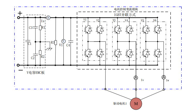
The main circuit of the controller is shown in the above diagram. The DC current sensor Is, voltage acquisition circuit V1 (integrated on the control board), discharge resistor R3, support capacitor C4, motor controller conversion module V1~V6, AC current sensors ISV, ISW, Y capacitors C2~C3, X capacitor C1, intermediate resistors R1~R2, and electrical connection lines and busbars constitute the components. The functional descriptions of each component and circuit are as follows:
Discharge Resistor——After the high-voltage DC power supply is disconnected, the discharge resistor releases the charge on the support capacitor to prevent electric shock.
DC Support Capacitor——Stabilizes the DC voltage and provides reactive power to the motor.
DC Current Sensor——Detects the DC current value flowing into the controller.
AC Current Sensor——Detects the V and W phase line currents of the motor.
Introduction to the Working Principle of the Cooling System
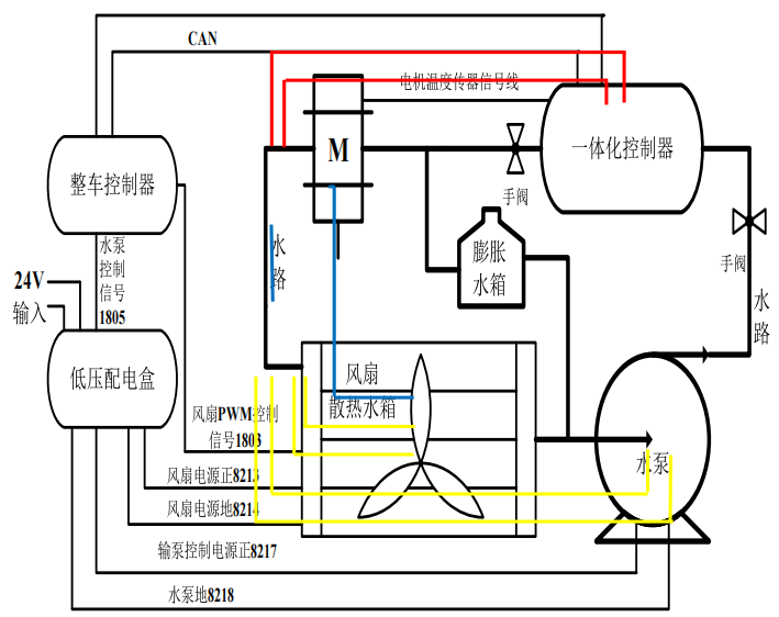
1. Water Pump Start-Stop Strategy:
The motor controller starts at 45℃ and stops at 38℃, the drive motor starts at 85℃ and stops at 70℃.
2. Fan Start-Stop Strategy:
The motor controller starts at 58℃ and stops at 46℃, the drive motor starts at 95℃ and stops at 85℃.
Fault Codes:
1641: Motor controller (limping) reaches the power reduction temperature threshold of 75℃
1642: Motor controller (stopping) reaches the power reduction temperature threshold of 80℃
1644: Drive motor (limping) reaches the power reduction temperature threshold of 135℃
1645: Drive motor (stopping) reaches the power reduction temperature threshold of 165℃
Troubleshooting Ideas:
1. Insufficient coolant, wiring harness, or connector faults.
2. Water pump or fan not working, water pump performance degradation.
3. Motor temperature sensor failure; (NIC 100KΩ approximately) PT100 (120Ω) (Temperature calculation formula = (actual resistance value – 100) / 0.385)
4. Integrated controller failure.
5. Residual air or debris blockage in the water circulation channel.
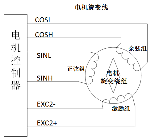
Working Principle:
The motor controller connects to the motor’s resolver windings through a resolver line. First, the motor controller outputs a fixed sine waveform to the excitation winding of the resolver. The change in the rotor position of the motor affects the amplitude and phase of the cosine and sine groups. The resolver decoding chip decodes the sine and cosine waveforms, calculating the motor angle, position, speed, and other data; real-time monitoring and data transmission.
51: Motor resolver fault, the motor controller detects a large deviation in the initial positioning angle of the motor resolver (exceeding 15°)
99: Resolver fault, motor overspeed;
Troubleshooting Ideas:
1. Motor angle deviation
2. Resolver winding fault
3. Signal line connection error
4. Excitation line connection error
5. Motor body fault
6. Program mismatch with the motor
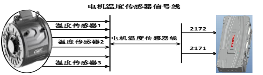
Introduction to Motor Temperature Sensors
Working Principle:
There are three groups of temperature sensors inside the drive motor output, the integrated controller only collects one group of motor temperature values, and the other two groups are backups.
1679, 1680: Motor sensor fault, motor temperature sensor short circuit or open circuit fault
Troubleshooting:
1. Check if the motor sensor contact lines are normal
2. Check if the motor sensor resistance value is around 120Ω (NTC sensor resistance value should be around 10KΩ)
3. Check the low-voltage harness X2 connector on the integrated controller for pin retraction
4. Check if the program matches the motor
02Common Fault Troubleshooting Methods
1. Overcurrent Fault
Definition
The three-phase large line AC output to the motor, the current sensor configured on the line collects the output current, which is compared on the control board through a comparator and the set current threshold voltage, outputting an overcurrent fault signal, which sends the corresponding fault code to the instrument display via CAN.
Fault Causes
(1) Phase loss: Poor contact of high-voltage large line, drive board issues, IGBT issues
(2) Detection causes: Issues with current sensors, wiring harness, control board in the detection circuit
(3) Real overcurrent: System matching issues
Troubleshooting Steps
(1) Check the connection of the three-phase AC line between the controller and the motor
(2) Check the connection of the motor resolver and wiring harness
(3) Check the wiring harness and connector of the AC output bus current sensor, measure the power supply (generally 5V) with a multimeter
(4) Measure the entire sampling circuit from the current sensor to the CPLD (difficult to operate on-site, not recommended)
(5) Check the drive board and IGBT
(6) Replace the current sensor step by step; replace the control board, re-flash the program; replace the drive board; replace the IGBT
Module Fault
Definition
The drive board detects that the voltage between the IGBT’s C and E exceeds the protection trigger value, actual module faults also include drive board undervoltage faults
Fault Causes
(1) Undervoltage: Drive board issues, power supply issues, short circuit between IGBT’s G and E
(2) Detection causes: Issues with the drive board, wiring harness, connector in the detection circuit
Troubleshooting Steps
(1) Visually check for burnt or visibly damaged components, circuit boards, use a multimeter to measure the IGBT, measure the resistance between the gate and emitter, check the wiring harness and connectors from the drive board to the gate driver board
(2) Check for cold solder joints on the gate driver board, check for poor adhesive points on connectors (may have melted glue causing poor contact), measure the power supply of the drive board
(3) Replace the drive board; if ineffective, short-circuit the C and E terminals in the output socket of the 12-channel drive board, if no fault occurs, it is basically determined to be caused by the IGBT or gate driver board
(4) Replace the gate driver board or IGBT
…… For more content, please contact customer service to unlock
 END
END
Truck Maintenance Academy
Learn truck maintenance at Truck Maintenance Academy
Learn truck maintenance team management at Truck Maintenance Academy
Learn commercial vehicle aftermarket operations at Truck Maintenance Academy
Scan to Add
Scan to add Xiao Wei
Learn maintenance knowledge with Xiao Wei

Click
Read the original text to learn more about commercial vehicle maintenance insights
Note: The content of the article is sourced from the internet, please contact the author for copyright issues