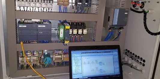
Practical tips for daily applications of PLCs, hoping to assist everyone in their daily use of PLCs.
The grounding requirements for PLC systems are quite strict, and it is best to have an independent dedicated grounding system. Also, ensure that other devices related to the PLC are reliably grounded.
When multiple circuit grounding points are connected together, unexpected currents can arise, leading to logical errors or circuit damage.
The reasons for different grounding potentials usually stem from grounding points being physically separated too far apart. When devices that are far apart are connected by communication cables or sensors, the current between the cable and ground can flow throughout the circuit. Even over short distances, the load current of large devices can cause variations between their ground potentials or generate unpredictable currents through electromagnetic effects.
Between incorrect grounding points, there is a potential for devastating currents to arise in the circuit, which can damage equipment.
PLC systems generally adopt a single-point grounding method. To improve resistance to common-mode interference, shielding floating ground technology can be used for analog signals, where the shielding layer of the signal cable is grounded at one point, and the signal circuit is floating, with insulation resistance to ground not less than 50MΩ.
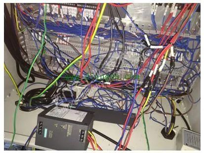
The industrial environment is quite harsh, with many high and low-frequency interferences. These interferences are generally introduced to the PLC through cables connected to field devices.
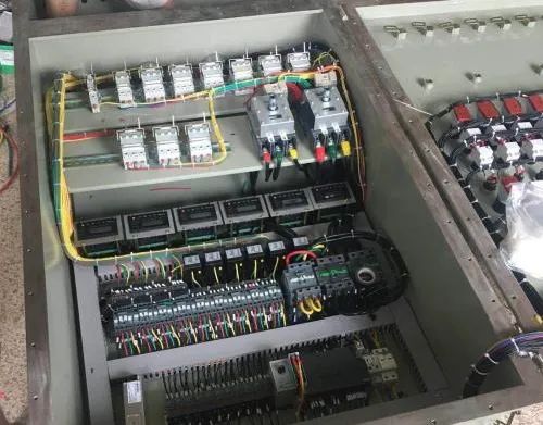
In addition to grounding measures, attention should be paid to implementing some anti-interference measures in the design and construction of cables:
(1) Analog signals are small signals and are easily affected by external interference; double-shielded cables should be used;
(2) High-speed pulse signals (such as pulse sensors, counting disks, etc.) should use shielded cables to prevent external interference and to prevent high-speed pulse signals from interfering with low-level signals;
(3) Communication cables between PLCs typically operate at higher frequencies, and it is generally advisable to use cables provided by the manufacturer. If requirements are not high, shielded twisted pair cables can be used;
(4) Analog signal lines and DC signal lines should not be routed in the same cable tray as AC signal lines;
(5) Shielded cables brought into and out of the control cabinet must be grounded and should connect directly to the equipment without passing through terminal blocks;
(6) AC signals, DC signals, and analog signals should not share a single cable; power cables should be laid separately from signal cables.
(7) During on-site maintenance, methods to resolve interference include: using shielded cables for the affected lines and re-routing; adding anti-interference filtering code in the program.
Eliminating Inter-Cable Capacitance to Avoid Malfunctions
There is capacitance between the conductors of the cable, and qualified cables can limit this capacitance within a certain range.
Even with qualified cables, when the cable length exceeds a certain distance, the capacitance value between the lines may exceed the required value. When this cable is used for PLC input, inter-cable capacitance may cause PLC malfunctions, resulting in many inexplicable phenomena.
These phenomena mainly manifest as: the wiring appears correct, but the PLC has no input; the PLC has inputs that should not be present, and lacks inputs that should be present, meaning PLC inputs interfere with each other. To resolve this issue, the following should be done:
(1) Use twisted cables with the conductors twisted together;
(2) Minimize the length of the cables used;
(3) Use separate cables for inputs that interfere with each other;
Selection of Output Modules
Output modules are divided into transistor, bidirectional thyristor, and contact types:
(1) Transistor types have the fastest switching speed (generally 0.2ms), but the load capacity is the smallest, about 0.2~0.3A, 24VDC, suitable for fast switching and signal connections, generally connected with frequency converters, DC devices, etc. Attention should be paid to the impact of transistor leakage current on the load.
(2) The advantage of thyristor types is that they are contactless and have AC load characteristics, but their load capacity is limited.
(3) Relay outputs have AC and DC load characteristics and high load capacity. In conventional control, relay contact type outputs are generally selected first, but their disadvantage is that the switching speed is slow, generally around 10ms, making them unsuitable for high-frequency switching applications.
Handling Overvoltage and Overcurrent in Frequency Converters
(1) When reducing the setpoint to decelerate the motor, the motor enters regenerative braking mode. The energy fed back to the frequency converter is also high, and this energy is stored in the filter capacitor, causing the voltage across the capacitor to rise and quickly reach the set value for DC overvoltage protection, resulting in the frequency converter tripping.
The solution is to add a braking resistor externally to the frequency converter, using this resistor to dissipate the regenerative energy fed back from the motor to the DC side.
(2) When a frequency converter drives multiple small motors, if one small motor experiences an overcurrent fault, the frequency converter will report an overcurrent fault alarm, causing the frequency converter to trip and stopping other normal small motors from working.
Solution: Install a 1:1 isolation transformer on the output side of the frequency converter. When one or several small motors experience an overcurrent fault, the fault current will impact the transformer instead of the frequency converter, thus preventing the frequency converter from tripping. After testing, it worked well, and the previous issue of normal motors also stopping was resolved.
Labeling Inputs and Outputs for Easy Maintenance
The PLC controls a complex system, and what can be seen are two rows of staggered input and output relay terminals, corresponding indicator lights, and PLC numbers, much like an integrated circuit with dozens of pins. If anyone attempts to troubleshoot a faulty device without looking at the schematic, they will be at a loss, and the speed of fault finding will be particularly slow. In light of this, we create a table based on the electrical schematic, which is posted on the equipment control console or control cabinet, indicating each PLC input and output terminal number along with the corresponding electrical symbols and Chinese names, similar to the function descriptions of each pin of an integrated circuit.
With this input-output table, electricians familiar with the operation process or the ladder diagram of the equipment can begin troubleshooting.
However, for those unfamiliar with the operation process and unable to read ladder diagrams, a second table needs to be created: the PLC input-output logic function table. This table actually explains the logical correspondence between input circuits (trigger elements, associated elements) and output circuits (executive elements) during most operations.
Practical experience has shown that if you can skillfully utilize the input-output correspondence table and the input-output logic function table, you can troubleshoot electrical faults easily without needing diagrams.
Inferring Faults Through Program Logic
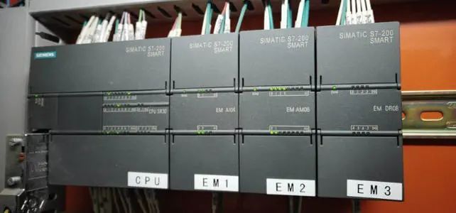
Currently, there are many types of PLCs commonly used in industry. For low-end PLCs, the ladder diagram instructions are quite similar, while for mid to high-end models, such as the S7-300, many programs are written in table language.
Practical ladder diagrams must have Chinese symbol annotations; otherwise, reading them can be quite challenging. If one has a general understanding of the equipment process or operation before looking at the ladder diagram, it becomes easier to interpret.
For electrical fault analysis, the reverse lookup method or reverse inference method is generally used, which involves finding the corresponding PLC output relay from the fault point based on the input-output correspondence table and starting to trace back the logical relationships that satisfy its action.
Experience indicates that once a problem is identified, the fault can generally be ruled out, as it is rare for two or more fault points to occur simultaneously in equipment.
In general, PLCs are extremely reliable devices with a very low failure rate. The probability of hardware damage such as PLCs or CPUs or software errors is almost zero. PLC input points are unlikely to be damaged unless caused by strong electrical intrusion, and the normally open points of PLC output relays have a long lifespan unless short-circuited by peripheral loads or designed improperly with excessive load current.
Therefore, when searching for electrical fault points, the focus should be on the peripheral electrical components controlled by the PLC, rather than suspecting the PLC hardware or program, which is crucial for quickly repairing faulty equipment and restoring production.
Thus, the focus of the author’s discussion on troubleshooting electrical faults in PLC control circuits is not on the PLC itself, but rather on the peripheral electrical components within the PLC-controlled circuit.
Fully Utilizing Software and Hardware Resources
(1) Instructions that do not participate in the control loop or have already been activated before the loop should not be entered into the PLC;
(2) When multiple instructions control a single task, they can be connected in parallel externally before being input to a single input point;
(3) Make full use of the internal functional software components of the PLC, fully invoke intermediate states to ensure the program’s completeness and coherence, which also reduces hardware investment and lowers costs;
(4) Where conditions permit, it is best to operate each output independently for easy control and inspection, and to protect other output circuits; when one output point fails, only the corresponding output circuit will lose control;
(5) If the output is for forward/reverse control of a load, not only should interlocks be implemented in the PLC internal program, but external measures should also be taken to prevent the load from operating in both directions;
(6) Emergency stops for the PLC should use external switches to ensure safety.
(1) Do not connect AC power lines to input terminals to avoid damaging the PLC;
(2) Ground terminals should be independently grounded and not connected in series with other devices; the cross-sectional area of the grounding wire should not be less than 2mm²;
(3) Auxiliary power supplies have a small power output and can only drive small power devices (such as photoelectric sensors);
(4) Some PLCs have a limited number of occupied points (i.e., unused terminal addresses), so do not connect wires to them;
(5) When there is no protection in the PLC output circuit, protective devices such as fuses should be used in the external circuit to prevent damage from load short circuits.
Disclaimer:This article is reproduced from the internet, and the copyright belongs to the original author. If there are any copyright issues, please contact us for deletion. Thank you!
Complete question bank for the 2022 junior electrician exam (includes answers)
Three essential tools for electricians, accessible with one click on WeChat!
【Collection】 The “path” for veteran electricians over ten years, the secret to earning over ten thousand a month!
Which of the five major electrical drawing software (CAD, Eplan, CADe_simu…) do you choose?
The latest electrical version of CAD drawing software, with a super detailed installation tutorial!
The latest electrical drawing software EPLAN, with a super detailed installation tutorial!
Common issues for beginners using S7-200 SMART programming software (includes download link)
Comprehensive electrical calculation EXCEL sheets, automatically generated! Electrical calculations made easy!
Bluetooth headsets, electrician/PLC beginner books given away? Come claim your electrical gifts!
Basic skills for PLC programming: ladder diagrams and control circuits (includes 1164 practical cases for Mitsubishi PLCs)
Still can’t understand electrical diagrams? Basics of electrician interpretation, simulation software available for quick hands-on practice!
12 free electrician video courses, 10GB of software/e-book materials, and 30 days of free electrician live classes are available!
Don’t forget to like and follow!