EtherCAT is a commonly used industrial field bus that features a flexible network topology, simple system configuration, and intuitive operation similar to field bus systems. Additionally, due to the low implementation cost of EtherCAT, it has become a viable option in situations where field bus networks were previously not applicable.
Next, we will use Huichuan 5U PLC and Huichuan SV660 servo to complete EtherCAT bus control.
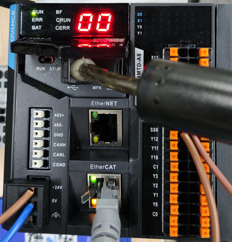
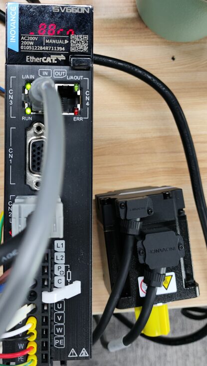
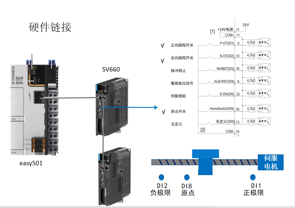
1. First, connect the communication line; plug the port under the PLC into the driver CN3 port, and that’s it, no configuration is needed for the driver. (If there is a second servo, you can connect a wire from the CN4 port of the first servo to the CN3 port of the next servo, and so on. The 5U PLC supports up to 32-axis control.)
▲Click the image to enlarge
2. Next, connect the wiring for the nine-pin serial port of the servo driver. The main signals that need to be connected are three (positive limit, negative limit, origin), and the servo enable can be controlled directly via communication. Alarm reset can also be connected. The wiring diagram is as follows:
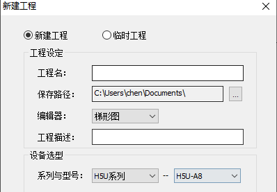
Then create a new project and select the corresponding PLC model.
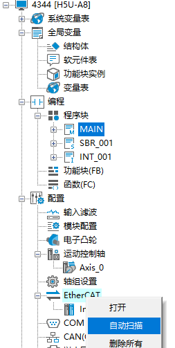
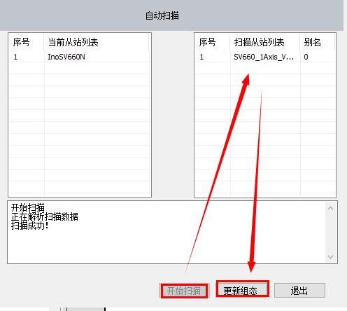
3. After that, right-click on EtherCAT and select auto-scan to recognize the servo driver.
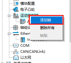
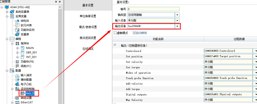
4. Then right-click on the motion control axis, click “Add Axis”, double-click the added axis, select the output device as the previously scanned servo device, and then you can download the program into the PLC.
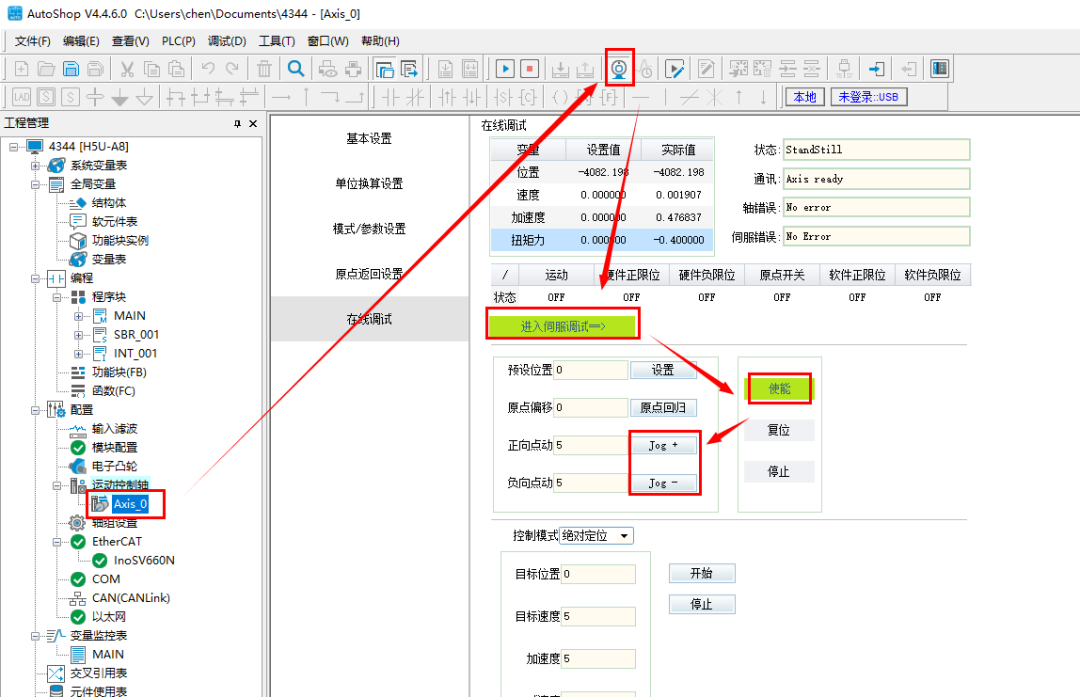
5.、 Then click the monitoring icon to enter servo axis debugging. After clicking the enable button, the motor will be enabled and locked. Click “jog+” to rotate forward, and click “jog-” to rotate backward. The servo test is successful, and you can then write the corresponding program to control it.
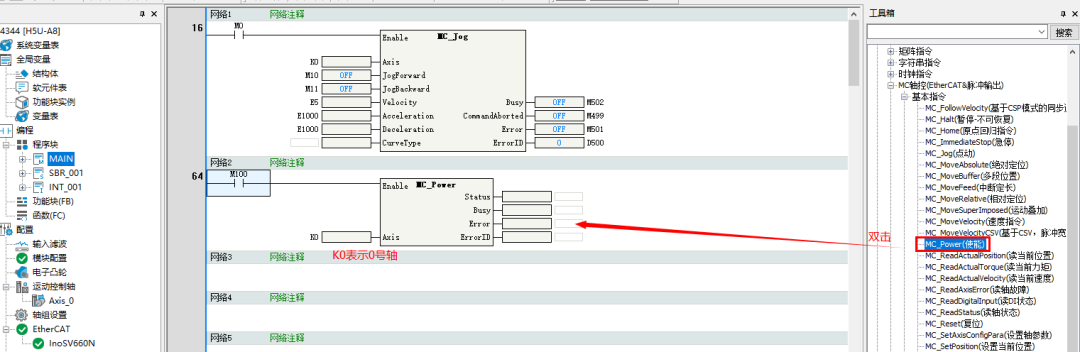
6. Enable: Pull over the enable block; when M100 is on, the servo will be enabled, allowing positioning control.
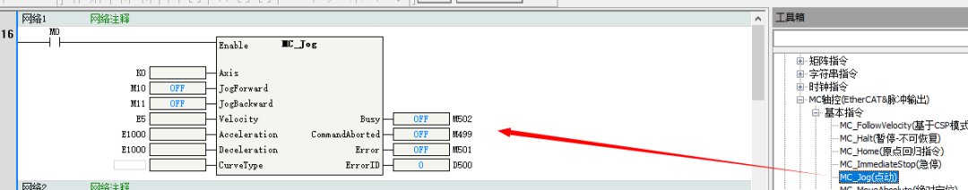
7. Manual JOG: Drag the JOG block over; the first K0 represents axis 0. When M0 is on, the axis will start rotating, needing to be combined with M10 or M11. M10 represents forward rotation, and M11 represents backward rotation (for other points, when your mouse hovers over the corresponding pin, the corresponding Chinese meaning will automatically display, showing its function).
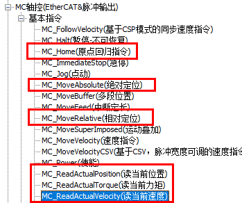
8. Relative positioning, absolute positioning, origin return, current position, speed, and torque all have their own blocks that can be set individually.
Alright, this article explains everything up to this point. You can learn more about the detailed functions through practical operations.
Source: Jicheng Training Network, Author: Jicheng – Chen Yuxin, unauthorized reproduction is prohibited!


Complete Mitsubishi PLC Documentation Package
Long press the QR code to receive immediately
Previous Recommendations
64 Essential Siemens E-books for Automation Learning | Free Download
Mitsubishi FX-TRN Learning Software Error Handling Methods
[Essential for Beginners] Do You Understand the Base Conversion Necessary for Learning PLC?
Mitsubishi PLC Manual Stepper Motor Control Case
GT Works3 Batch Monitoring IO Points, Completed with Just 2 Screens.
A Must-See! FX3U and Mitsubishi E800 Frequency Converter Dedicated Instruction Communication Applications!