·First, we need to design the Proteus simulation as usual. After designing the simulation, we will write embedded code for the 8051 microcontroller. I will design the code in the Keil uVision3 compiler, and the 8051 microcontroller I will use is the AT89C51. So, let’s first start with the Proteus simulation to implement the interface between the LCD and the 8051 microcontroller.
Note: A free project download link is provided at the end of the article.
Proteus Simulation
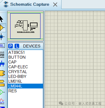
·Open your Proteus software and obtain the following components from the Proteus component library:
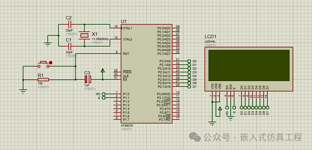
·Now, design a circuit in Proteus using the components mentioned above, as shown in the figure below:
Writing Code
I use Keil uVision 3 software to write the code. Before starting the LCD programming, let me clarify some basic concepts. In the LCD, we need to send two types of data.
oThe first type is commands, for example, we need to tell the LCD whether to start from the first column or the second column, so we need to position the LCD cursor at a specific location where we want to start writing. This type of data is referred to as LCD commands.
oThe second type of data is the actual data we need to print on the LCD.
oTherefore, first we send a command to the LCD, such as moving the cursor to the second line, and then we send the actual data that will start printing at that point.
The first function I use is called lcdinit(), which initializes the LCD and sends the initialization command to it.
void lcdinit(void)
{
///////////// Reset process from datasheet /////////
delay(15000);
writecmd(0x30);
delay(4500);
writecmd(0x30);
delay(300);
writecmd(0x30);
delay(650);
/////////////////////////////////////////////////////
writecmd(0x38); //function set
writecmd(0x0c); //display on,cursor off,blink off
writecmd(0x01); //clear display
writecmd(0x06); //entry mode, set increment
}
Now in this function, I use another function called writecmd, as shown below:
void writecmd(int z)
{
RS = 0; // => RS = 0
P2 = z; //Data transfer
E = 1; // => E = 1
delay(150);
E = 0; // => E = 0
delay(150);
}
To send commands to the LCD using the 8051 microcontroller, we must set the RS pin to low, then send the data and toggle the Enable pin from high to low, as I did in the writecmd() function above. The next function we use is the writedata() function, as shown below:
void writedata(char t)
{
RS = 1; // => RS = 1
P2 = t; //Data transfer
E = 1; // => E = 1
delay(150);
E = 0; // => E = 0
delay(150);
}
Therefore, if you check the above two functions, it is clear that when we send a command to the LCD, we must set the RS pin to 0, but when we need to send data to be printed on the LCD, we need to set the RS pin to 1. This is the only thing worth understanding when interfacing the LCD with the 8051 microcontroller. Below is the complete code for the interface between the LCD and the 8051 microcontroller.
#include
//Function declarations
void cct_init(void);
void delay(int);
void lcdinit(void);
void writecmd(int);
void writedata(char);
void ReturnHome(void);
//*******************
//Pin description
/*
P2 is data bus
P1.0 is RS
P1.1 is E
*/
//********************
// Defines Pins
sbit RS = P1^0;
sbit E = P1^1;
// ***********************************************************
// Main program
//
void main(void)
{
cct_init(); //Make all ports zero
lcdinit(); //Initilize LCD
writecmd(0x81);
writedata(‘E’);
writedata(‘m’);
writedata(‘b’);
writedata(‘e’);
writedata(‘d’);
writedata(‘d’);
writedata(‘e’);
writedata(‘d’);
writedata(‘ ‘);
writedata(‘S’);
writedata(‘i’);
writedata(‘m’);
writedata(‘u’);
writedata(‘l’);
writedata(‘a’);
writedata(‘t’);
writedata(‘i’);
writedata(‘o’);
writedata(‘n’);
writecmd(0xc4);
writedata(‘H’);
writedata(‘e’);
writedata(‘l’);
writedata(‘l’);
writedata(‘o’);
writedata(‘ ‘);
writedata(‘W’);
writedata(‘o’);
writedata(‘r’);
writedata(‘l’);
writedata(‘d’);
ReturnHome(); //Return to 0 position
while(1)
{
}
}
void cct_init(void)
{
P0 = 0x00; //not used
P1 = 0x00; //not used
P2 = 0x00; //used as data port
P3 = 0x00; //used for generating E and RS
}
void delay(int a)
{
int i;
for(i=0;i <a;i++); </a;i++);//null statement
}
void writedata(char t)
{
RS = 1; // => RS = 1
P2 = t; //Data transfer
E = 1; // => E = 1
delay(150);
E = 0; // => E = 0
delay(150);
}
void writecmd(int z)
{
RS = 0; // => RS = 0
P2 = z; //Data transfer
E = 1; // => E = 1
delay(150);
E = 0; // => E = 0
delay(150);
}
void lcdinit(void)
{
///////////// Reset process from datasheet /////////
delay(15000);
writecmd(0x30);
delay(4500);
writecmd(0x30);
delay(300);
writecmd(0x30);
delay(650);
/////////////////////////////////////////////////////
writecmd(0x38); //function set
writecmd(0x0c); //display on,cursor off,blink off
writecmd(0x01); //clear display
writecmd(0x06); //entry mode, set increment
}
void ReturnHome(void) //Return to 0 location
{
writecmd(0x02);
delay(1500);
}
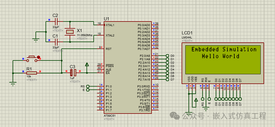
Place this code into Keil software and compile to generate a hex file. Upload this hex file to Proteus software and run it. If everything goes well, you will see the content as shown in the figure below:
 Project download link:
Link: https://pan.baidu.com/s/1yZW00cQsIKPszruEyqusOg?pwd=nf6u Extraction code: nf6u