Follow our public account, click the “···” in the upper right corner of the homepage, set it as a star, and stay updated on the latest news in smart automotive electronics and software.
The CAN bus is a serial data communication protocol developed to solve data exchange between numerous control and testing instruments in modern vehicles. It is a multi-master bus, and the communication medium can be twisted pair, coaxial cable, or optical fiber. For the automotive industry, its real-time performance, flexibility, reliability, low cost, and good fault diagnosis and error correction capabilities are highly attractive and have significant market potential. As a means of connecting controllers, CAN is widely used in vehicles of various brands for controlling the engine, transmission, ABS, and other safety modules, mainly based on the CAN network. It is believed that CAN technology will become a new path for development in the automotive field.
CAN stands for Controller Area Network, developed by the German company BOSCH, renowned for its automotive electronic products, and it has ultimately become an international standard (ISO 11898). It is one of the most widely used field buses internationally. Due to its high performance, high reliability, and unique design, the CAN bus has gained increasing attention. In North America and Western Europe, the CAN bus protocol has become the standard bus for automotive computer control systems and embedded industrial control local area networks, and it has a J1939 protocol designed specifically for large trucks and heavy machinery vehicles based on CAN as the underlying protocol.
This article mainly introduces CAN bus technology, in-depth research on the characteristics, advantages, and applications of the CAN communication protocol for automobiles.
CAN is short for Controller Area Network (hereinafter referred to as CAN), which is an ISO standardized serial communication protocol. In the automotive industry, various electronic control systems have been developed due to the demands for safety, comfort, convenience, low pollution, and low cost. Since the data types used for communication between these systems and their reliability requirements vary, many situations involve multiple buses, leading to an increase in the number of wiring harnesses. To meet the needs of “reducing the number of wiring harnesses” and “high-speed communication of large amounts of data across multiple LANs,” the German electrical company Bosch developed the CAN communication protocol for automobiles in 1986. Subsequently, CAN was standardized through ISO11898 and ISO11519, and it has become the standard protocol for automotive networks in Europe.
CAN’s high performance and reliability have been recognized and widely applied in industrial automation, shipping, medical devices, industrial equipment, and more. Field buses are one of the hot topics in today’s automation technology development and are known as the computer local area network of the automation field. Their emergence provides strong technical support for real-time and reliable data communication between nodes in distributed control systems.
2 Advantages
CAN belongs to the category of field buses and is an effective serial communication network that supports distributed control or real-time control. Compared to many RS-485-based distributed control systems, distributed control systems based on the CAN bus have significant advantages in the following aspects:
2.1 Strong Real-Time Data Communication Between Network Nodes
First, CAN controllers operate in various modes, and each node in the network can compete to send data to the bus using a lossless structure of bit-wise arbitration based on bus access priority (determined by message identifier). The CAN protocol eliminates station address encoding and instead encodes the communication data, allowing different nodes to receive the same data simultaneously. These characteristics make data communication between nodes in a CAN bus network highly real-time and easy to form redundant structures, enhancing system reliability and flexibility. In contrast, RS-485 can only form a master-slave structured system, and the communication method can only be through master polling, resulting in poorer real-time performance and reliability.
2.2 Shortened Development Cycle
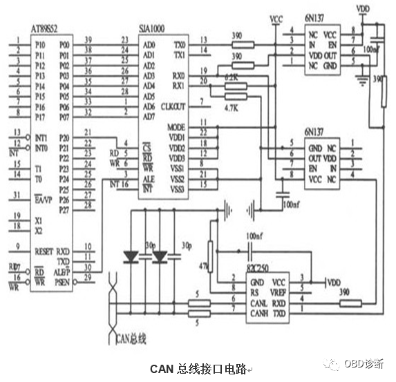
The CAN bus connects to the physical bus via the two output terminals CANH and CANL of the CAN transceiver interface chip 82C250, with the CANH terminal being either high level or floating, while the CANL terminal can only be low level or floating. This ensures that the phenomenon seen in RS-485 networks, where multiple nodes simultaneously send data to the bus and cause a short circuit, resulting in damage to some nodes, does not occur. Moreover, CAN nodes have an automatic output shutdown function in case of severe errors, preventing the operations of other nodes on the bus from being affected, thus ensuring that the bus does not enter a “deadlock” state due to issues with individual nodes. Additionally, the complete communication protocol of CAN can be implemented by CAN controller chips and their interface chips, significantly reducing system development difficulty and shortening the development cycle—advantages that RS-485, with only electrical protocols, cannot match.
2.3 Established International Standard Field Bus
Furthermore, compared to other field buses, the CAN bus has many characteristics such as high communication speed, ease of implementation, and cost-effectiveness, making it an established international standard field bus. These factors are also crucial reasons for CAN bus applications in numerous fields and its strong market competitiveness.
2.4 One of the Most Promising Field Buses
CAN, or Controller Area Network, belongs to the category of industrial field buses. Compared to general communication buses, the CAN bus data communication exhibits outstanding reliability, real-time performance, and flexibility. Due to its excellent performance and unique design, the CAN bus is increasingly gaining attention. Its application in the automotive field is the most widespread, with some famous automobile manufacturers worldwide, such as BENZ, BMW, PORSCHE, ROLLS-ROYCE, and JAGUAR, using the CAN bus for data communication between the internal control systems of vehicles and various detection and execution mechanisms. Additionally, due to the inherent characteristics of the CAN bus, its application scope has expanded beyond the automotive industry to include automatic control, aerospace, marine, process industries, machinery, textile machinery, agricultural machinery, robotics, CNC machine tools, medical devices, and sensors. CAN has become an international standard and is recognized as one of the most promising field buses. Typical application protocols include: SAEJ1939/ISO11783, CANOpen, CANaerospace, DeviceNet, NMEA 2000, etc.
The following are explanations of some concepts and features of the media access control sublayer of the CAN protocol:
(1) Message: Data on the bus is sent in different message formats, but the length is limited. When the bus is idle, any node on the network can send a message.
(2) Information Routing: In CAN, nodes do not use any messages about system configuration, such as station addresses; the receiving node determines whether to receive a frame of information based on the characteristics of the message itself. Therefore, when expanding the system, there is no need to change the application layer or any node’s software and hardware, and nodes can be added directly to CAN.
(3) Identifier: The message to be transmitted has a characteristic identifier (which is a field in data frames and remote frames), which indicates not the target node address but the characteristics of the message itself. Information is broadcasted over the network, and all nodes can receive it. Nodes determine whether to receive a frame of information based on the identifier.
(4) Data Consistency: It must ensure that messages are received simultaneously by all nodes in CAN or not at all, which is achieved in conjunction with error handling and resynchronization functions.
(5) Bit Transmission Rate: Different CAN systems have different speeds, but within a given system, the bit transmission rate is unique and fixed.
(6) Priority: The priority of the message occupying the bus is determined by the identifier in the sent data. The smaller the identifier, the higher the priority.
(7) Remote Data Request: By sending a remote frame, nodes that need data request another node to send the corresponding data. The responding node transmits the data frame named with the same identifier as the requested data remote frame.
(8) Arbitration: As long as the bus is idle, any node can send a message to the bus. If two or more nodes send messages simultaneously, a bus access collision will occur. This collision can be resolved using bit-wise arbitration based on identifiers. The arbitration mechanism ensures that neither messages nor time are lost. When data frames and remote frames with the same identifier are sent simultaneously, data frames take precedence over remote frames. During arbitration, each sender compares the level of the sent bit with the monitored bus level. If the levels are the same, the unit can continue sending; if a “dominant” level is sent while a “recessive” level is monitored, that unit loses arbitration and must exit the sending state.
(9) Bus State: The bus has two states: “dominant” and “recessive”; “dominant” corresponds to logic “0”, and “recessive” corresponds to logic “1”. The dominant state and recessive state are for the dominant state; thus, when two nodes send “0” and “1” simultaneously, the bus presents “0”. The CAN bus uses non-return to zero (NRZ) encoding, so the bus is either “0” or “1”. However, the CAN protocol does not specifically define the implementation methods for these two states.
(10) Fault Confinement: CAN nodes can distinguish between faults caused by transient disturbances and permanent faults. Faulty nodes will be shut down.
(11) Acknowledgment: Receiving nodes acknowledge correctly received messages and mark inconsistent messages.
(12) The maximum communication distance of CAN is 10 kilometers (assuming a rate of 5Kbps) or a maximum communication rate of 1Mbps (assuming a communication distance of 40 meters).
(13) The number of nodes on the CAN bus can reach up to 110. The communication medium can be twisted pair, coaxial cable, or optical fiber.
(14) Messages have a short frame structure, and the short transmission time reduces the probability of interference. CAN has a good error-checking mechanism, which ensures the reliability of CAN communication.
The CAN bus is a serial data communication protocol developed by the German company BOSCH in the early 1980s to solve data exchange between numerous control and testing instruments in modern vehicles. It is a multi-master bus, and the communication medium can be twisted pair, coaxial cable, or optical fiber. The communication rate can reach up to 1Mbps.
Completion of Frame Processing for Communication Data
The CAN bus communication interface integrates the physical layer and data link layer functions of the CAN protocol, completing frame processing for communication data, including bit stuffing, data block encoding, cyclic redundancy check, and priority determination.
Making the Number of Nodes in the Network Theoretically Unlimited
One of the greatest features of the CAN protocol is the elimination of traditional station address encoding, replaced by encoding communication data blocks. This method allows the number of nodes in the network to be theoretically unlimited, with data block identifiers consisting of 11-bit or 29-bit binary arrays, thus defining 2 or more different data blocks. This method of encoding by data block also allows different nodes to receive the same data simultaneously, which is very useful in distributed control systems. The maximum data segment length is 8 bytes, which meets the general requirements for control commands, operational statuses, and test data in typical industrial fields. At the same time, 8 bytes do not consume too much bus time, ensuring real-time communication. The CAN protocol uses CRC checks and provides corresponding error handling functions, ensuring the reliability of data communication. The outstanding characteristics, high reliability, and unique design of CAN make it particularly suitable for interconnecting industrial process monitoring devices, thus gaining increasing attention in the industry and being recognized as one of the most promising field buses.
Free Communication Between Nodes
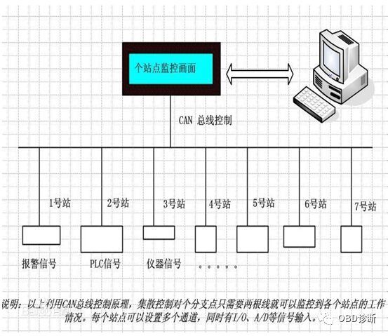
The CAN bus adopts a multi-master competitive bus structure, featuring multi-master operation and decentralized arbitration, as well as broadcast communication. Any node on the CAN bus can actively send information to other nodes on the network at any time without distinguishing between master and slave, thus enabling free communication between nodes. The CAN bus protocol has been certified by the International Organization for Standardization, and its technology is relatively mature, with control chips already commercialized, offering high cost-performance, especially suitable for data communication between distributed measurement and control systems. CAN bus cards can be inserted into any PC AT XT compatible machine, conveniently forming distributed monitoring systems.
Only two wires are connected to the outside, and an internal error detection and management module is integrated.
Transmission Distance and Rate
Features of the CAN bus: (1) Data communication does not distinguish between master and slave; any node can initiate data communication with any other (one or more) nodes, relying on the priority order of information from each node to determine the communication sequence, with high-priority node information communicating in 134μs; (2) When multiple nodes initiate communication simultaneously, lower-priority nodes yield to higher-priority ones, preventing congestion on the communication line; (3) The maximum communication distance can reach 10KM (at a rate below 5Kbps), and the rate can reach 1Mbps (when the communication distance is less than 40M); (4) The transmission medium for the CAN bus can be twisted pair or coaxial cable. The CAN bus is suitable for large data volume short-distance communication or long-distance small data volume communication, with high real-time requirements, used in multi-master multi-slave or equal-status field environments.
To process data in real-time, data must be transmitted quickly, which requires a high-speed physical transmission path. When several stations need to send data simultaneously, a rapid bus allocation is required. Real-time processing of urgent data exchanged over the network varies significantly. A rapidly changing physical quantity, such as engine load, will transmit data more frequently and require shorter delays than a relatively slowly changing physical quantity, such as engine temperature.
CAN transmits data in units of messages, and the priority of messages is embedded in the 11-bit identifier, with the lowest binary number having the highest priority. Once this priority is established during system design, it cannot be changed. Conflicts in bus reading can be resolved through bit arbitration. When several stations send messages simultaneously, Station 1’s message identifier is 011111; Station 2’s message identifier is 0100110; Station 3’s message identifier is 0100111. All identifiers have the same first two bits of 01 until the third bit is compared, at which point Station 1’s message is dropped because its third bit is high while the other two stations’ third bits are low. The fourth, fifth, and sixth bits of Station 2 and Station 3 messages are the same until the seventh bit, at which point Station 3’s message is dropped. Note that the signals on the bus continue to track the message of the station that has gained bus reading authority. In this example, Station 2’s message is being tracked. The advantage of this non-destructive bit arbitration method is that the beginning portion of the message has already been transmitted over the network before it is finally determined which station’s message will be sent. All stations that do not gain bus reading authority become receiving stations with the highest priority message, and will not send messages until the bus is free again.
CAN’s high efficiency is due to the fact that the bus is only utilized by those stations that have pending requests for bus access, and these requests are processed in order based on the importance of the message throughout the system. This approach offers many advantages when the network is heavily loaded because the priority of bus reading has been sequentially placed in each message, ensuring lower individual latency times in real-time systems.
For the reliability of master stations, CAN protocol implements decentralized bus control, where all primary communications, including bus reading (permission) control, are completed in several stages within the system. This is the only way to achieve a highly reliable communication system.
Comparison of CAN with Other Communication Solutions
In practice, there are two important bus allocation methods: scheduled allocation and demand allocation. In the first method, each node is allocated according to the maximum duration regardless of whether each node requests the bus. Thus, the bus can be allocated to each station and is unique to that station, regardless of whether it accesses the bus immediately or at a specific time. This ensures clear bus allocation during bus access. In the second method, the bus is allocated to a station based on the basic requirements for data transmission, and the bus system allocates based on the transmission preferences of the stations (e.g., Ethernet CSMA/CD). Therefore, when multiple stations request bus access simultaneously, the bus will terminate all stations’ requests, and no station will gain bus allocation. To allocate the bus, more than one bus access is necessary.
The method of bus allocation implemented by CAN ensures explicit bus allocation when different stations request bus access. This bit arbitration method can resolve collision problems that arise when two stations simultaneously send data. Unlike Ethernet networks’ message arbitration, CAN’s non-destructive resolution of bus access conflicts ensures that the bus is not occupied without transmitting useful messages. Even under heavy bus loads, bus access based on message content has proven to be an effective system. Although the bus’s transmission capacity may be insufficient, all unresolved transmission requests are processed in order of importance. In networks like CSMA/CD, such as Ethernet, the system often crashes due to overload, a situation that does not occur in CAN.
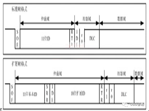 The messages transmitted on the bus consist of seven parts per frame. The CAN protocol supports two message formats, differing only in the length of the identifier (ID), with the standard format being 11 bits and the extended format being 29 bits.
In the standard format, the start bit of the message is called the frame start (SOF), followed by the arbitration field consisting of an 11-bit identifier and a remote transmission request bit (RTR). The RTR bit indicates whether it is a data frame or a request frame, with no data bytes in the request frame.
The control field includes an identifier extension bit (IDe), indicating whether it is a standard format or extended format. It also includes a reserved bit (ro) for future expansion use. The last four bits indicate the length of data in the data field (DLC). The data field ranges from 0 to 8 bytes, followed by a cyclic redundancy check (CRC) for error detection.
The acknowledgment field (ACK) includes an acknowledgment bit and an acknowledgment delimiter. Both bits sent by the sending station are recessive (logical 1), at which point the receiving station that correctly receives the message sends a dominant level (logical 0) to override it. This method ensures that the sending station can confirm that at least one station in the network has correctly received the message.
The end of the message is marked by the frame end. There is a very short interval between adjacent frames; if no station accesses the bus during this time, the bus will remain idle.
Composition of CAN Data Frames
The remote frame consists of six fields: frame start, arbitration field, control field, CRC field, acknowledgment field, and frame end. There is no data field in the remote frame.
The RTR bit of the remote frame must be recessive.
The data value of DLC is independent and can be any value from 0 to 8, corresponding to the data length of the data frame.
The error frame consists of two different fields: the first field is obtained by superimposing error flags from each station, and the second field is the error delimiter.
Error flags have two forms:
Active error flag, consisting of six consecutive dominant bits.
Passive error flag, consisting of six consecutive recessive bits.
The error delimiter consists of eight recessive bits.
The overload frame includes two bit fields: overload flag and overload delimiter.
Conditions for sending an overload frame:
Requesting a delay for the next data frame or remote frame.
Detecting a dominant bit in the interval field.
The overload flag consists of six dominant bits.
The overload delimiter consists of eight recessive bits.
Unlike other buses, the CAN protocol cannot use acknowledgment information. In fact, it can signal any error that occurs. The CAN protocol can use five methods for error checking, with the first three based on message content.
3.4.1 Cyclic Redundancy Check (CRC)
Adding redundancy check bits to a frame can ensure the correctness of the message. The receiving station can determine if the message has errors through CRC.
This method checks the format and size of the frame through bit fields to determine the correctness of the message, used for checking format errors.
3.4.3 Acknowledgment Error
As mentioned earlier, the received frame is confirmed by the receiving station through an explicit acknowledgment. If the sending station does not receive an acknowledgment, it indicates that the receiving station found an error in the frame, meaning the ACK field is damaged or no station in the network received the message. The CAN protocol can also detect errors through bit checking.
Sometimes, a node in CAN can monitor the signals it sends. Therefore, the sending station can observe the bus level and detect differences between sent and received bits.
Each bit in a frame is represented by a non-return to zero code, ensuring maximum efficiency of bit encoding. However, if there are too many consecutive bits of the same level in a frame, synchronization may be lost. To ensure synchronization, bit stuffing is used to generate synchronization edges. After five consecutive equal bits, the sending station automatically inserts a complementary bit; during reception, this stuffing bit is automatically discarded. For example, after five consecutive low-level bits, CAN automatically inserts a high-level bit. CAN checks for errors using this encoding rule; if there are six equal bits in a frame, CAN knows an error has occurred.
If at least one station detects one or more errors through the above methods, it will send an error flag to terminate the current transmission. This prevents other stations from receiving erroneous messages and ensures consistency of messages on the network. After a significant amount of data is terminated, the sending station will automatically resend the data. As a rule, it will restart sending within 23 bit periods after detecting an error. In special cases, the system’s recovery time is 31 bit periods.
However, this method has a problem, as a faulty station will cause all data to be terminated, including correct data. Therefore, if self-monitoring measures are not taken, the bus system should adopt a modular design. For this reason, the CAN protocol provides a way to differentiate transient errors from permanent errors and local station failures. This can be achieved by evaluating the error statistics of the faulty station, allowing a station to determine its own errors and enter an operational mode that does not adversely affect other stations, meaning that a station can prevent normal data from being erroneously terminated by shutting itself down.
Hard Synchronization and Resynchronization
Hard synchronization occurs only when a transition from recessive to dominant occurs in idle bus conditions, indicating the start of message transmission. After hard synchronization, the bit time counter restarts counting with the synchronization segment. Hard synchronization forcibly places the already occurred transition within the re-started bit time synchronization segment. According to synchronization rules, if a hard synchronization occurs within a bit time, no resynchronization will occur within that bit time. Resynchronization may extend phase buffer segment 1 or shorten phase buffer segment 2. The upper limits of the extension time or shortening time for these two phase buffer segments are given by the resynchronization jump width (SJW).
To prevent the vehicle from posing dangers to the driver due to data exchange errors during its lifespan, the safety system of the vehicle requires high reliability in data transmission. If the reliability of data transmission is sufficiently high, or the residual data errors are sufficiently low, this goal is not difficult to achieve. From the perspective of the bus system’s data, reliability can be understood as the ability to identify data errors arising from the transmission process.
The probability of residual data errors can be obtained through statistical measurements of data transmission reliability. It describes the probability of transmitted data being corrupted and this corruption not being detectable. The probability of residual data errors must be very small, making it nearly undetectable over the entire lifespan of the system. Calculating the probability of residual errors requires the ability to classify data errors and a transmission path that can be described by a model. To determine the residual error probability of CAN, we can treat the probability of residual errors as a function of the bit error probability during the transmission of messages with 80 to 90 bits, assuming that there are 5 to 10 stations in this system and the error rate is 1/1000, the maximum bit error probability would be in the order of 10—13. For example, the maximum data transmission rate of the CAN network is 1Mbps; if the data transmission capability is only utilized at 50%, then for a system with a working lifespan of 4000 hours and an average message length of 80 bits, the total amount of data transmitted would be 9×10¹⁰. During the operational lifespan of the system, the statistically average undetectable transmission error is less than 10—2. In other words, if a system operates based on a daily schedule of 365 days, 8 hours a day, and an error rate of 0.7 per second, then statistically, an undetectable error would occur only once every 1000 years.
The messages transmitted on the bus consist of seven parts per frame. The CAN protocol supports two message formats, differing only in the length of the identifier (ID), with the standard format being 11 bits and the extended format being 29 bits.
In the standard format, the start bit of the message is called the frame start (SOF), followed by the arbitration field consisting of an 11-bit identifier and a remote transmission request bit (RTR). The RTR bit indicates whether it is a data frame or a request frame, with no data bytes in the request frame.
The control field includes an identifier extension bit (IDe), indicating whether it is a standard format or extended format. It also includes a reserved bit (ro) for future expansion use. The last four bits indicate the length of data in the data field (DLC). The data field ranges from 0 to 8 bytes, followed by a cyclic redundancy check (CRC) for error detection.
The acknowledgment field (ACK) includes an acknowledgment bit and an acknowledgment delimiter. Both bits sent by the sending station are recessive (logical 1), at which point the receiving station that correctly receives the message sends a dominant level (logical 0) to override it. This method ensures that the sending station can confirm that at least one station in the network has correctly received the message.
The end of the message is marked by the frame end. There is a very short interval between adjacent frames; if no station accesses the bus during this time, the bus will remain idle.
Composition of CAN Data Frames
The remote frame consists of six fields: frame start, arbitration field, control field, CRC field, acknowledgment field, and frame end. There is no data field in the remote frame.
The RTR bit of the remote frame must be recessive.
The data value of DLC is independent and can be any value from 0 to 8, corresponding to the data length of the data frame.
The error frame consists of two different fields: the first field is obtained by superimposing error flags from each station, and the second field is the error delimiter.
Error flags have two forms:
Active error flag, consisting of six consecutive dominant bits.
Passive error flag, consisting of six consecutive recessive bits.
The error delimiter consists of eight recessive bits.
The overload frame includes two bit fields: overload flag and overload delimiter.
Conditions for sending an overload frame:
Requesting a delay for the next data frame or remote frame.
Detecting a dominant bit in the interval field.
The overload flag consists of six dominant bits.
The overload delimiter consists of eight recessive bits.
Unlike other buses, the CAN protocol cannot use acknowledgment information. In fact, it can signal any error that occurs. The CAN protocol can use five methods for error checking, with the first three based on message content.
3.4.1 Cyclic Redundancy Check (CRC)
Adding redundancy check bits to a frame can ensure the correctness of the message. The receiving station can determine if the message has errors through CRC.
This method checks the format and size of the frame through bit fields to determine the correctness of the message, used for checking format errors.
3.4.3 Acknowledgment Error
As mentioned earlier, the received frame is confirmed by the receiving station through an explicit acknowledgment. If the sending station does not receive an acknowledgment, it indicates that the receiving station found an error in the frame, meaning the ACK field is damaged or no station in the network received the message. The CAN protocol can also detect errors through bit checking.
Sometimes, a node in CAN can monitor the signals it sends. Therefore, the sending station can observe the bus level and detect differences between sent and received bits.
Each bit in a frame is represented by a non-return to zero code, ensuring maximum efficiency of bit encoding. However, if there are too many consecutive bits of the same level in a frame, synchronization may be lost. To ensure synchronization, bit stuffing is used to generate synchronization edges. After five consecutive equal bits, the sending station automatically inserts a complementary bit; during reception, this stuffing bit is automatically discarded. For example, after five consecutive low-level bits, CAN automatically inserts a high-level bit. CAN checks for errors using this encoding rule; if there are six equal bits in a frame, CAN knows an error has occurred.
If at least one station detects one or more errors through the above methods, it will send an error flag to terminate the current transmission. This prevents other stations from receiving erroneous messages and ensures consistency of messages on the network. After a significant amount of data is terminated, the sending station will automatically resend the data. As a rule, it will restart sending within 23 bit periods after detecting an error. In special cases, the system’s recovery time is 31 bit periods.
However, this method has a problem, as a faulty station will cause all data to be terminated, including correct data. Therefore, if self-monitoring measures are not taken, the bus system should adopt a modular design. For this reason, the CAN protocol provides a way to differentiate transient errors from permanent errors and local station failures. This can be achieved by evaluating the error statistics of the faulty station, allowing a station to determine its own errors and enter an operational mode that does not adversely affect other stations, meaning that a station can prevent normal data from being erroneously terminated by shutting itself down.
Hard Synchronization and Resynchronization
Hard synchronization occurs only when a transition from recessive to dominant occurs in idle bus conditions, indicating the start of message transmission. After hard synchronization, the bit time counter restarts counting with the synchronization segment. Hard synchronization forcibly places the already occurred transition within the re-started bit time synchronization segment. According to synchronization rules, if a hard synchronization occurs within a bit time, no resynchronization will occur within that bit time. Resynchronization may extend phase buffer segment 1 or shorten phase buffer segment 2. The upper limits of the extension time or shortening time for these two phase buffer segments are given by the resynchronization jump width (SJW).
To prevent the vehicle from posing dangers to the driver due to data exchange errors during its lifespan, the safety system of the vehicle requires high reliability in data transmission. If the reliability of data transmission is sufficiently high, or the residual data errors are sufficiently low, this goal is not difficult to achieve. From the perspective of the bus system’s data, reliability can be understood as the ability to identify data errors arising from the transmission process.
The probability of residual data errors can be obtained through statistical measurements of data transmission reliability. It describes the probability of transmitted data being corrupted and this corruption not being detectable. The probability of residual data errors must be very small, making it nearly undetectable over the entire lifespan of the system. Calculating the probability of residual errors requires the ability to classify data errors and a transmission path that can be described by a model. To determine the residual error probability of CAN, we can treat the probability of residual errors as a function of the bit error probability during the transmission of messages with 80 to 90 bits, assuming that there are 5 to 10 stations in this system and the error rate is 1/1000, the maximum bit error probability would be in the order of 10—13. For example, the maximum data transmission rate of the CAN network is 1Mbps; if the data transmission capability is only utilized at 50%, then for a system with a working lifespan of 4000 hours and an average message length of 80 bits, the total amount of data transmitted would be 9×10¹⁰. During the operational lifespan of the system, the statistically average undetectable transmission error is less than 10—2. In other words, if a system operates based on a daily schedule of 365 days, 8 hours a day, and an error rate of 0.7 per second, then statistically, an undetectable error would occur only once every 1000 years.
5 Application Examples
The CAN bus is mainly used in industrial control fields for low-speed fault-tolerant CAN according to the ISO11898-3 standard, while in the automotive field, a common usage rate is 500Kbps for high-speed CAN.
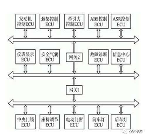
Internal Network System of the CAN Bus in Automobiles
Some imported models have multiple control networks for body, comfort, multimedia, etc., where body control uses the CAN network, comfort uses the LIN network, and multimedia uses the MOST network, with the CAN network as the main network controlling the engine, transmission, ABS, and other body safety modules, sharing data such as speed, vehicle speed, oil temperature, etc., throughout the vehicle, enabling intelligent control of the vehicle, such as automatically locking doors at high speeds and opening doors automatically when airbags deploy.
The CAN system is divided into high-speed and low-speed; high-speed CAN systems use hard wiring and operate at 500kbps to control ECU, ABS, etc.; low-speed CAN is comfort-oriented, operating at 125Kbps, mainly controlling instruments and anti-theft features.
A certain hospital has five 16T/H German Viessmann gas boilers providing 5kg/cm2 steam to facilities like laundry rooms, preparation rooms, supply rooms, domestic water, heating, etc., consuming 12 million cubic meters of natural gas and 200,000 tons of tap water annually. The hospital adopts a relay heating method for regional management of the heating network, divided into four major heating areas. Among them, the gas consumption for heating in winter is significant, leading to the design of an intelligent monitoring system for distributed boiler steam heating networks based on the CAN field bus. Field applications show that this building automation system has strong anti-interference capabilities, easy on-site configuration, high network integration, and user-friendly interfaces.
Eliminating traditional station address encoding, replaced by encoding communication data blocks, allows operation in a multi-master mode;
Using non-destructive arbitration technology, when two nodes transmit data to the network simultaneously, the lower-priority node actively stops data transmission while the higher-priority node can continue transmitting data without being affected, effectively avoiding bus conflicts;
Using a short frame structure, with each frame having an effective byte count of 8, short data transmission time, low probability of interference, and short resend time;
Each data frame has CRC checks and other error detection measures, ensuring high reliability of data transmission, suitable for use in high-interference environments;
Nodes have an automatic shutdown function in case of severe errors, cutting off their connection to the bus to avoid affecting other operations on the bus;
Data can be transmitted and received in point-to-point, one-to-many, and broadcast centralized methods.
Features include strong real-time performance, long transmission distances, strong electromagnetic interference resistance, and low costs;
Using a dual-wire serial communication method, strong error detection capabilities, and can work in high noise interference environments;
Prioritization and arbitration functions, allowing multiple control modules to connect to the CAN-Bus, forming a multi-master local network;
Can decide whether to receive or mask a message based on the message ID;
Reliable error handling and detection mechanisms;
Automatically resends information if the transmitted message is corrupted;
Nodes have the capability to automatically exit the bus in case of severe errors;
Messages do not contain source or target addresses, only using identifiers to indicate functional and priority information.
The CAN bus is widely used in industrial control and automotive fields. During the development and testing phase of the CAN bus, it is necessary to conduct development tests on its topology, node functions, network integration, etc. This requires virtual, semi-virtual, and fully physical simulation testing platforms, and it is essential to test whether each node complies with the error response mechanisms stipulated in ISO11898. Therefore, the development of the CAN bus requires specialized development testing tools, and a set of simple and user-friendly production line testing tools is also necessary during the production phase. Major suppliers of development testing tools for the CAN bus include ZLG, Passion IXXAT, IHR, Vector, Intrepidcs, Passion Warwick, LAIKE, etc. Commonly used development testing tools include CANScope, CANalyst-II, Passiontech DiagRA, canAnalyser, X-Analyser, AutoCAN, CANspider, LAIKE CANTest, etc.
There are five types of errors in the CAN bus, which do not exclude each other. Below is a brief introduction to their differences, causes, and handling methods.
Bit Error: When a node sends a bit to the bus while also monitoring the bus, if it detects a difference between the level of the bus bit and the level sent, a bit error is detected at that moment. However, sending a recessive bit during the filling bit flow period or acknowledgment gap is not considered an error. A sender that sends an acknowledgment error flag does not consider it an error when a dominant bit is detected.
Stuffing Error: A stuffing error is detected when the sixth consecutive bit level of the same type appears in a message encoded using bit stuffing.
CRC Error:CRC sequences consist of results calculated by the sender’s CRC. The receiver calculates the CRC in the same way as the sender. If the calculated result differs from the received CRC sequence, a CRC error is detected.
Form Error:When one or more illegal bits appear in a fixed form bit field, a form error is detected.
Acknowledgment Error:If the sender does not detect a dominant bit during the acknowledgment gap, it detects an acknowledgment error.
Nodes detecting error conditions will mark them by sending error flags. When any node detects a bit error, stuffing error, form error, or acknowledgment error, that node will send an error flag at the next bit.
When a CRC error is detected, the error flag starts to be sent after the acknowledgment delimiter unless the error flag for another error condition has already begun to be sent.
In the CAN bus, any unit may be in one of the following three fault states: error active state, error passive state, and bus off state.
An error active unit can participate in bus communication normally and sends an active error flag when an error is detected. An error passive node can participate in bus communication but is not allowed to send an active error flag. When it detects an error, it can only send a passive error flag and remains in the error passive state until the next initialization of sending.
The bus off state does not allow the unit to affect the bus in any way.
To define faults, each bus unit has two counters: a transmit error counter and a receive error counter. These counters are managed according to the following rules.
(1) When the receiver detects an error, the receiver error counter increases by 1, unless all detected errors occur during the sending of active error flags or overload flags.
(2) When the receiver detects a dominant bit after sending an error flag, the error counter increases by 8.
(3) When the sender sends an error flag, the sender error counter increases by 8. There are two exceptions: first, if the sender is error passive and has not detected a dominant acknowledgment or has detected an acknowledgment error, and when sending its passive error flag, it has not detected a dominant bit; second, if the arbitration device generates a stuffing error, the sender sends a recessive bit error flag while detecting a dominant bit. Outside of these two cases, the sender error counter does not change.
(4) When the sender sends an active error flag or overload flag and detects a bit error, the sender error counter increases by 8.
(5) After sending an active error flag, passive error flag, or overload error flag, any node is allowed a maximum of seven consecutive dominant bits. After detecting 11 consecutive dominant bits, or detecting eight consecutive dominant bits immediately following a passive error flag, and each sequence of eight additional consecutive dominant bits, the sender error counter for each sender increases by 8, and the receiver error counter for each receiver also increases by 8.
(6) After a message is successfully sent, the sender error counter decreases by 1 unless the counter value is already 0.
(7) After a message is successfully sent, if the receiver error counter is between 1 and 197, its value decreases by 1; if the receiver error counter is 0, it remains 0; if it is greater than 127, its value is recorded as a number between 119 and 127.
(8) When the sender error counter is equal to or greater than 128, or the receiver error counter is equal to or greater than 128, the node enters the error passive state and sends an active error flag.
(9) When the sender error counter is greater than or equal to 256, the node enters the bus off state.
(10) When both the sender error counter and the receiver error counter are less than or equal to 127, the error passive node reverts to an error active node.
(11) After detecting 11 consecutive recessive bits for 128 times on the bus, the bus off node will revert to an error active node when both error counters are 0.
(12) When the error counter value exceeds 96, it indicates that the bus is severely disturbed.
If only one node is connected to the bus during system startup, after this node sends a message, it will not receive an acknowledgment, detect an error, and repeat the message. At this point, the node can become an error passive node but will not cause the bus to shut down.
 Follow our public account, click the “···” in the upper right corner of the homepage, set it as a star, and stay updated on the latest news in smart automotive electronics and software.
【Disclaimer】The article represents the author’s independent viewpoint and does not represent the position of Wangcai Automotive Electronics. If there are issues with the content, copyright, etc., please contact Wangcai Automotive Electronics within 30 days of publication for deletion or copyright negotiation.