Source: https://blog.csdn.net/an520
UART, SPI, and I2C are very common serial communication methods in embedded development. The underlying principles of these communications are not difficult, but many beginners struggle to learn them.
Today, I will share some common low-level data transmission principles of communication.
UART Serial Port
UART: Universal Asynchronous Receiver-Transmitter. UART is the most common type of serial communication. Below is an animation of the serial port connection to a host computer and the application of RS232.
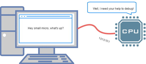
▲ Debugging MCU via UART on PC
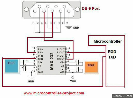
▲ RS-232 communication with MCU through level conversion chip
SPI Serial Communication
SPI: Serial Peripheral Interface. SPI is a common serial synchronous communication protocol with a wide range of applications.
Below is the timing diagram for SPI data transmission:
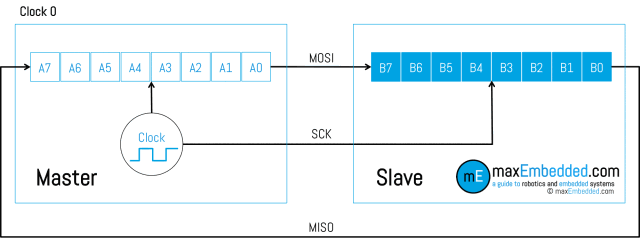
▲ SPI Data Transmission (1)
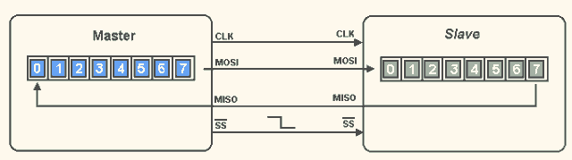
▲ SPI Data Transmission (2)
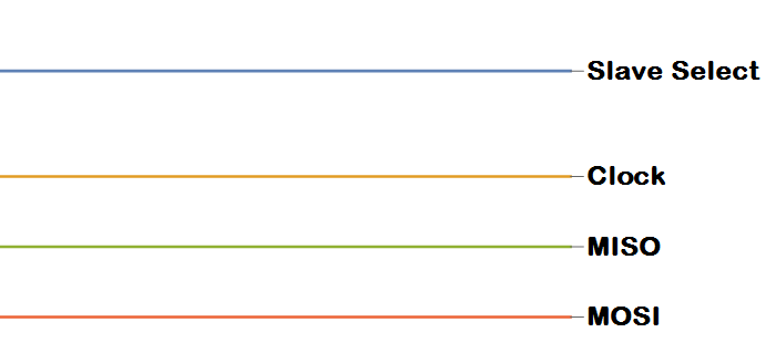
▲ SPI Timing Signals
I2C Communication
I²C: Inter-Integrated Circuit, literally meaning between integrated circuits, is abbreviated as I²C Bus. I²C mainly distinguishes slave devices through addresses, and its communication principle is relatively simple.
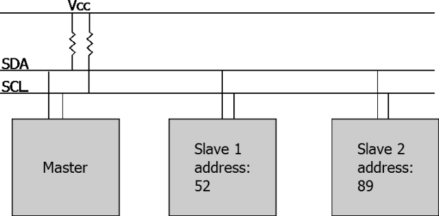
▲ I2C Bus and Addressing Method
Infrared Remote Control
Infrared remote control is quite common in our daily lives; most household remote controls use infrared. Infrared remote control communicates by controlling pulse width (the duration of high and low levels) and establishes a communication link through infrared wireless signals (it won’t work if blocked, but can reflect).
Infrared remote control is quite common in our daily lives; most household remote controls use infrared. Infrared remote control communicates by controlling pulse width (the duration of high and low levels) and establishes a communication link through infrared wireless signals (it won’t work if blocked, but can reflect).
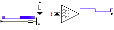
▲ Infrared control signal is also a serial communication signal
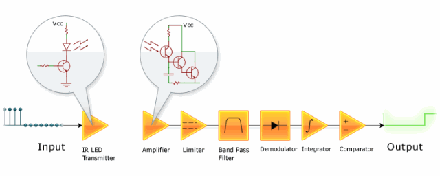
▲ Infrared signal reception and amplification shaping circuit
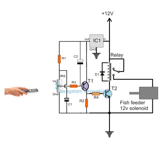
▲ A circuit for controlling a relay using an infrared receiver to feed fish
Serial to Parallel Conversion Circuit
Serial to parallel conversion means converting serial data into parallel data by controlling the clock to transmit serial data bit by bit, and when it reaches a whole (8 bits), it becomes parallel data. There are many ready-made chips for this converter, and the principle is very simple.
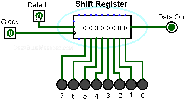
▲ Shift register with serial input and parallel output
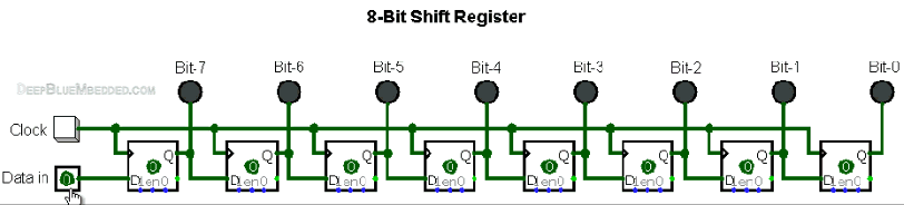
▲ Shift register composed of eight D flip-flops
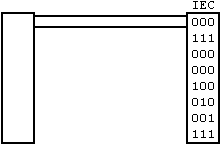
▲ Serial transmission schematic
Others
Here are some other principles of serial transmission (waveforms):
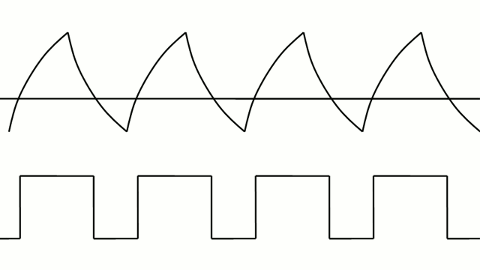
▲ PWM control of LED brightness
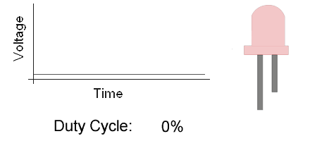
▲ PWM control of LED brightness
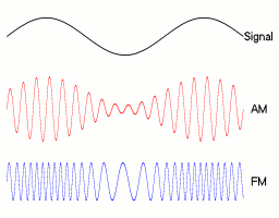
▲ Amplitude modulation and frequency modulation signals
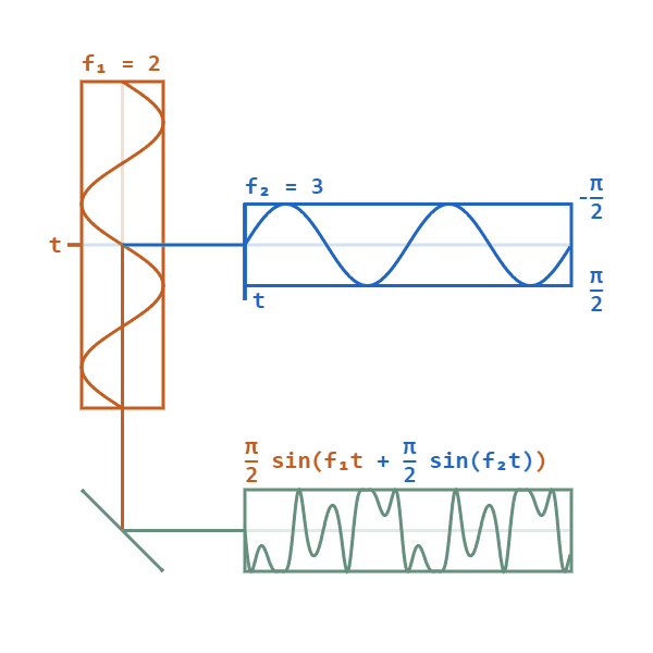
▲ Phase modulation signal
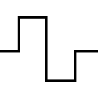
▲ Square wave edge jitter waveform
This article is sourced from the internet, freely conveying knowledge. Copyright belongs to the original author. If there are any copyright issues, please contact me for deletion.
Note
Due to recent changes in the WeChat public account push rules, to prevent missing articles, you can star and pin this account so that every article pushed will appear in your subscription list.
You may also like:
Easy to Understand | Step-by-Step Guide to Writing Your First Host Computer
General Library for Differential Upgrading Suitable for Embedded Systems!
Sharing a Highly Flexible Protocol Format (with Code Examples)
Sharing Some Practical Code Snippets (Part 2)
Sharing a Bug Localization Method You Might Not Know
Sharing a Method for Modifying Configuration Files
Embedded Miscellaneous Weekly Report Issue 13: lz4
Understanding Embedded Parallel Multithreading Processors!
Reply with 1024 in the WeChat chat interface to obtain embedded resources; reply with m to view article summaries