1Module Source>>>
Product Physical Display:

Data Download Link:http://www.lcdwiki.com/en/3.5inch_SPI_Module_ILI9488_SKU:MSP3520
2Specifications>>>
Operating Voltage:3.3V
Operating Current:20MA
Module Size:56.34(H) x 98.00(W)
Pixel Size:320(H) x 480(V)RGB
Driver Chip:ILI9488
Communication Protocol:SPI
Number of Pins Used:14 Pin (2.54mm pitch header)
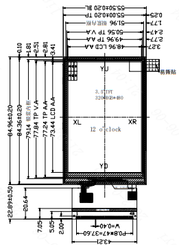
Size Parameters
3Porting Process>>>
Our goal is to port the example to the Lichuang CW32F030C8T6 development board. Follow the steps below to complete the porting.
- Import the source code into the project;
- Make rough modifications based on compilation errors;
- Modify pin configurations;
- Modify timing configurations;
- Porting verification.
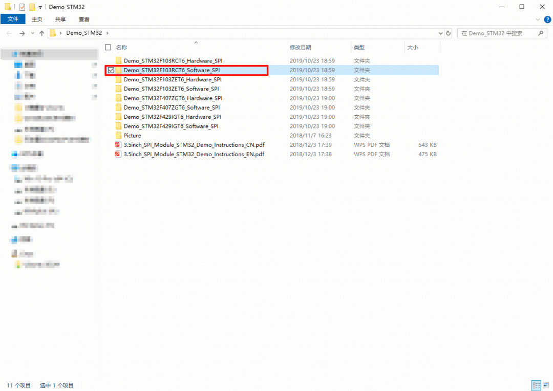
3.1View Data
Open the manufacturer’s data example (see example download for download). The specific path is shown in the figure below.
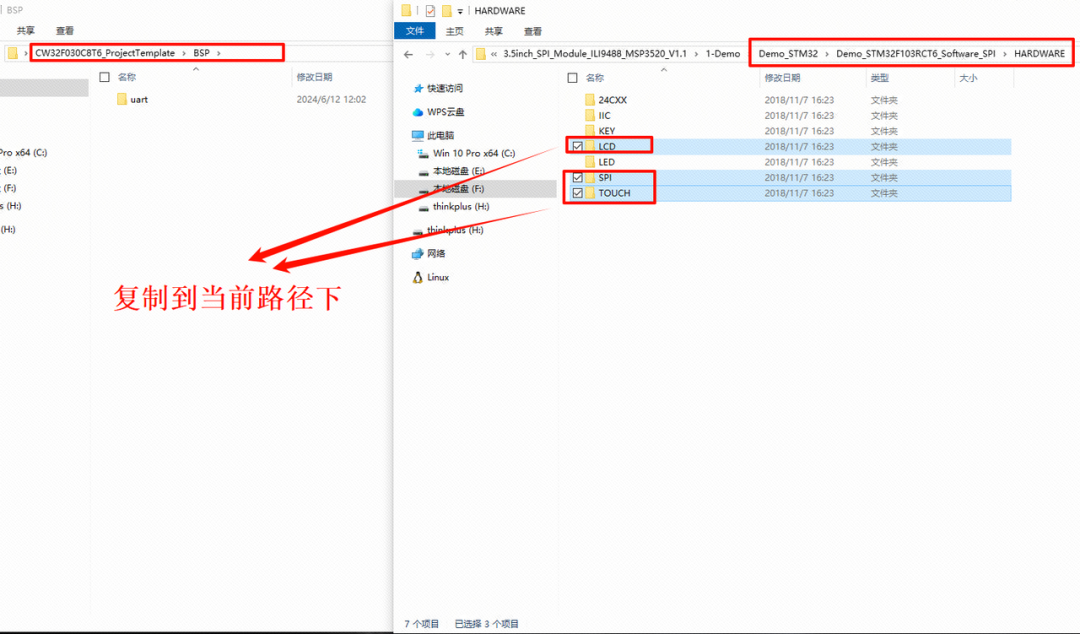 Copy Folder 1
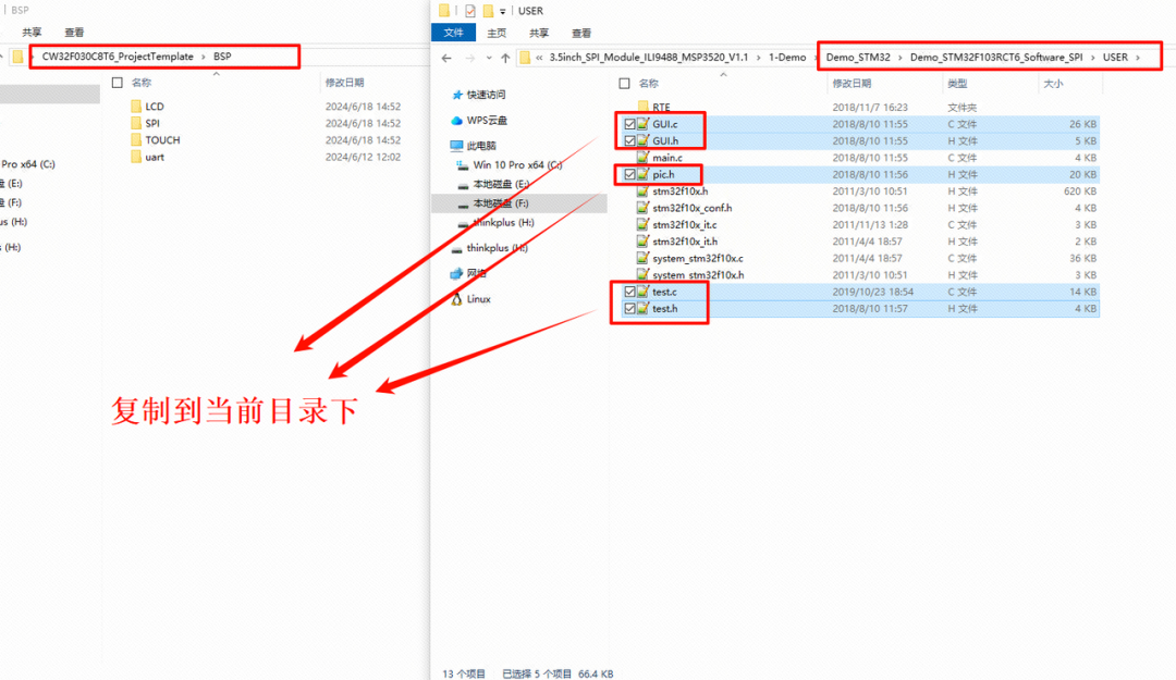 Copy Folder 2
Open your project and import the .c and .h files that we just copied.
https://wiki.lckfb.com/en/dwx-cw32f030c8t6/module/screen/3-5-ili9488-color-touch-screen.html#_2-%E8%A7%84%E6%A0%BC%E5%8F%82%E6%95%B0(Jump to the original text to view the animation)
Define three macros, u32, u16, and u8 in the lcd.h, touch.h, and spi.h files.
#include "board.h"#ifndef u8#define u8 uint8_t#endif#ifndef u16#define u16 uint16_t#endif#ifndef u32#define u32 uint32_t#endif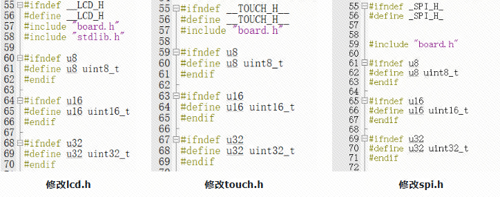
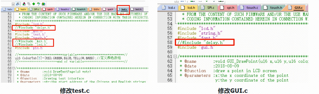
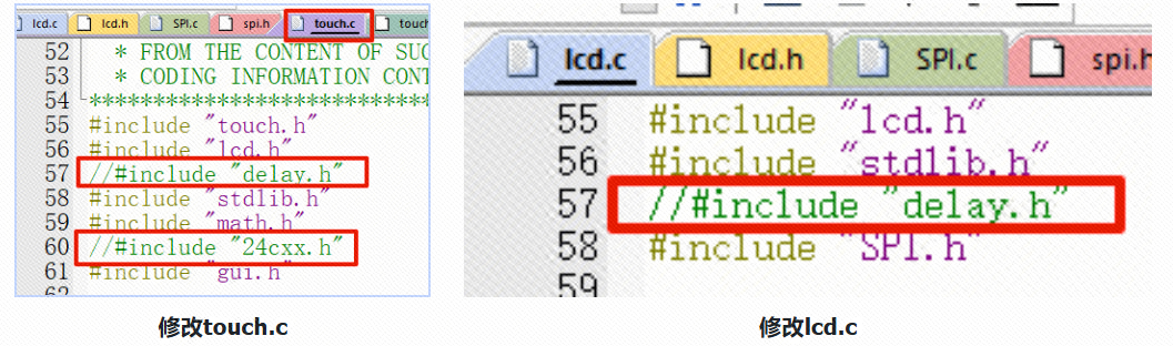
Comment out the delay.h header file in test.c, lcd.c, touch.c, and GUI.c files.
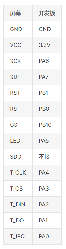
After selecting the pins, enter the project and start writing the screen pin initialization code.
3.4Port ModificationFor convenience in subsequent porting, I defined each pin in lcd.h as a macro, which can be modified as needed later.
//-----------------LCD Port Porting----------------#define RCC_LCD1_ENABLE() __RCC_GPIOA_CLK_ENABLE()#define RCC_LCD2_ENABLE() __RCC_GPIOB_CLK_ENABLE()//SCK#define PORT_LCD_SCL CW_GPIOA#define GPIO_LCD_SCL GPIO_PIN_6//MOSI#define PORT_LCD_SDA CW_GPIOA#define GPIO_LCD_SDA GPIO_PIN_7////MIS0//#define PORT_LCD_MIS GPIOB//#define GPIO_LCD_MIS GPIO_PIN_14//NSS#define PORT_LCD_CS CW_GPIOB#define GPIO_LCD_CS GPIO_PIN_10//DC#define PORT_LCD_DC CW_GPIOB#define GPIO_LCD_DC GPIO_PIN_0//RES#define PORT_LCD_RES CW_GPIOB#define GPIO_LCD_RES GPIO_PIN_1//BLK/LED#define PORT_LCD_BLK CW_GPIOA#define GPIO_LCD_BLK GPIO_PIN_5//CS2/T_CS#define PORT_LCD_CS2 CW_GPIOA#define GPIO_LCD_CS2 GPIO_PIN_3//PEN/T_IRQ#define PORT_LCD_PEN CW_GPIOA#define GPIO_LCD_PEN GPIO_PIN_0//T_CLK#define PORT_LCD_TCLK CW_GPIOA#define GPIO_LCD_TCLK GPIO_PIN_4//T_DIN#define PORT_LCD_TDIN CW_GPIOA#define GPIO_LCD_TDIN GPIO_PIN_2//T_DO#define PORT_LCD_TD0 CW_GPIOA#define GPIO_LCD_TD0 GPIO_PIN_1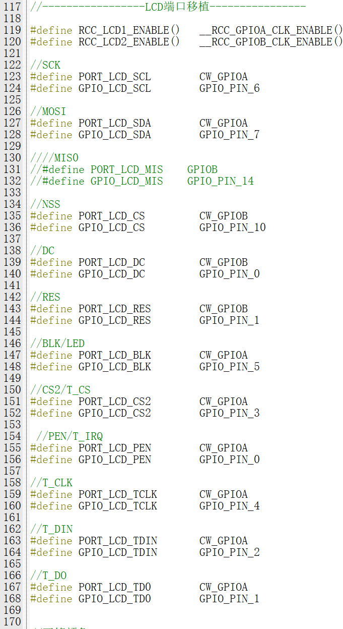 Software SPI Pin Macros
Modify the void LCD_GPIOInit(void) function in the lcd.c source code to the following code.
The code has already adapted the SPI pins. If you have not modified the related pins, set the macro definition USE_HARDWARE_SPI macro to 1.
void LCD_GPIOInit(void){    GPIO_InitTypeDef        GPIO_InitStruct; // GPIO initialization structure
    RCC_LCD1_ENABLE();        // Enable GPIO clock
    RCC_LCD2_ENABLE();        // Enable GPIO clock
    GPIO_InitStruct.Pins = GPIO_LCD_SCL|              // GPIO pins                           GPIO_LCD_SDA|                           GPIO_LCD_BLK;    GPIO_InitStruct.Mode = GPIO_MODE_OUTPUT_PP;       // Push-pull output    GPIO_InitStruct.Speed = GPIO_SPEED_HIGH;          // High output speed    GPIO_Init(PORT_LCD_SCL, &GPIO_InitStruct);        // Initialize
    GPIO_InitStruct.Pins = GPIO_LCD_DC|                           GPIO_LCD_RES|                           GPIO_LCD_CS;    GPIO_Init(PORT_LCD_CS, &GPIO_InitStruct);        // Initialize}
Modify the LCD Port Definition macro in lcd.h to:
//////////////////////////////////////////////////////////////////////-----------------LCD Port Definition----------------
//LCD control pin set to 1 operation statement macro definition#define        LCD_CS_SET          GPIO_WritePin(PORT_LCD_CS,  GPIO_LCD_CS,  GPIO_Pin_SET)#define        LCD_RS_SET          GPIO_WritePin(PORT_LCD_DC,  GPIO_LCD_DC,  GPIO_Pin_SET)#define        LCD_SDA_SET         GPIO_WritePin(PORT_LCD_SDA, GPIO_LCD_SDA, GPIO_Pin_SET)#define        LCD_SCL_SET         GPIO_WritePin(PORT_LCD_SCL, GPIO_LCD_SCL, GPIO_Pin_SET)#define        LCD_RST_SET         GPIO_WritePin(PORT_LCD_RES, GPIO_LCD_RES, GPIO_Pin_SET)#define        LCD_LED_SET         GPIO_WritePin(PORT_LCD_BLK, GPIO_LCD_BLK, GPIO_Pin_SET)
//LCD control pin set to 0 operation statement macro definition#define        LCD_CS_CLR          GPIO_WritePin(PORT_LCD_CS,  GPIO_LCD_CS,  GPIO_Pin_RESET)//CS#define        LCD_RS_CLR          GPIO_WritePin(PORT_LCD_DC,  GPIO_LCD_DC,  GPIO_Pin_RESET)//DC#define        LCD_SDA_CLR         GPIO_WritePin(PORT_LCD_SDA, GPIO_LCD_SDA, GPIO_Pin_RESET)//SDA=MOSI#define        LCD_SCL_CLR         GPIO_WritePin(PORT_LCD_SCL, GPIO_LCD_SCL, GPIO_Pin_RESET)//SCL=SCLK#define        LCD_RST_CLR         GPIO_WritePin(PORT_LCD_RES, GPIO_LCD_RES, GPIO_Pin_RESET)//RES#define        LCD_LED_CLR         GPIO_WritePin(PORT_LCD_BLK, GPIO_LCD_BLK, GPIO_Pin_RESET)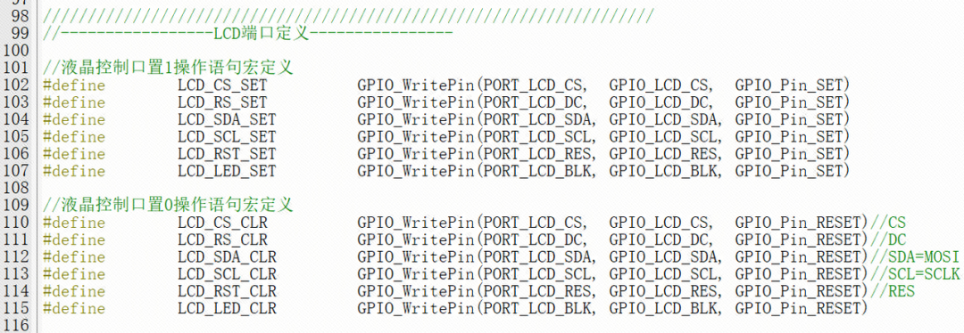
3.5Driver ModificationIn the SPI.c file, find the void SPIv_WriteData(unsigned char Data) function and modify it as follows.
void  SPIv_WriteData(u8 Data){    unsigned char i=0;    for(i=8;i>0;i--)    {        if(Data&0x80)                LCD_SDA_SET; //Output data        else                LCD_SDA_CLR;
        LCD_SCL_CLR;        LCD_SCL_SET;        Data<<=1;    }}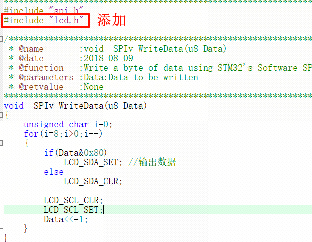
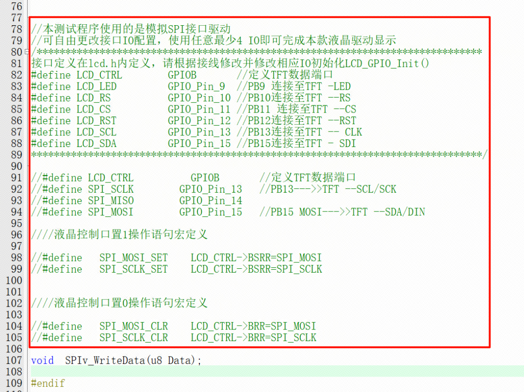
In spi.h, the manufacturer defined macros for the SPI interface. Here we will comment them out and use our own method.
Open the touch.c file and modify the following content:
- Modify the u8 TP_Init(void); function
u8 TP_Init(void){    GPIO_InitTypeDef  GPIO_InitStructure;
    /* PEN */    GPIO_InitStructure.Pins  = GPIO_LCD_PEN;    GPIO_InitStructure.Mode  = GPIO_MODE_INPUT_PULLUP; // Pull-up input    GPIO_InitStructure.Speed = GPIO_SPEED_HIGH;    GPIO_Init(PORT_LCD_PEN, &GPIO_InitStructure);
    /* DOUT*/    GPIO_InitStructure.Pins  = GPIO_LCD_TD0;    GPIO_InitStructure.Mode  = GPIO_MODE_INPUT_PULLUP; // Pull-up input    GPIO_InitStructure.Speed = GPIO_SPEED_HIGH;    GPIO_Init(PORT_LCD_TD0, &GPIO_InitStructure);
    /* TDIN*/    GPIO_InitStructure.Pins  = GPIO_LCD_TDIN;    GPIO_InitStructure.Mode  = GPIO_MODE_OUTPUT_PP;//Push-pull output mode    GPIO_InitStructure.Speed = GPIO_SPEED_HIGH;    GPIO_Init(PORT_LCD_TDIN, &GPIO_InitStructure);
    /* TCLK*/    GPIO_InitStructure.Pins  = GPIO_LCD_TCLK;    GPIO_InitStructure.Mode  = GPIO_MODE_OUTPUT_PP;//Push-pull output mode    GPIO_InitStructure.Speed = GPIO_SPEED_HIGH;    GPIO_Init(PORT_LCD_TCLK, &GPIO_InitStructure);
    /* TCS*/    GPIO_InitStructure.Pins  = GPIO_LCD_CS2;    GPIO_InitStructure.Mode  = GPIO_MODE_OUTPUT_PP;//Push-pull output mode    GPIO_InitStructure.Speed = GPIO_SPEED_HIGH;    GPIO_Init(PORT_LCD_CS2, &GPIO_InitStructure);
TP_Read_XY(&tp_dev.x,&tp_dev.y);//First read initialization return 1;}- Comment out the void TP_Save_Adjdata(void); and u8 TP_Get_Adjdata(void); functions.
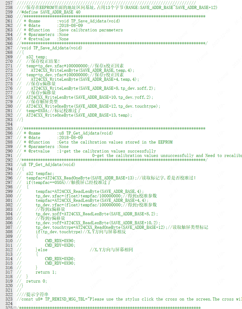
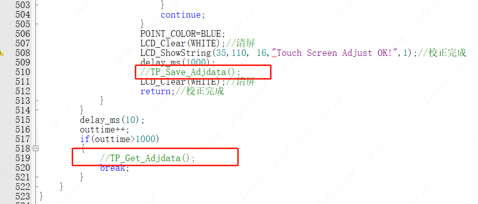
- Find the void TP_Adjust(void); function and comment out the TP_Save_Adjdata(); and TP_Get_Adjdata(); inside the function.
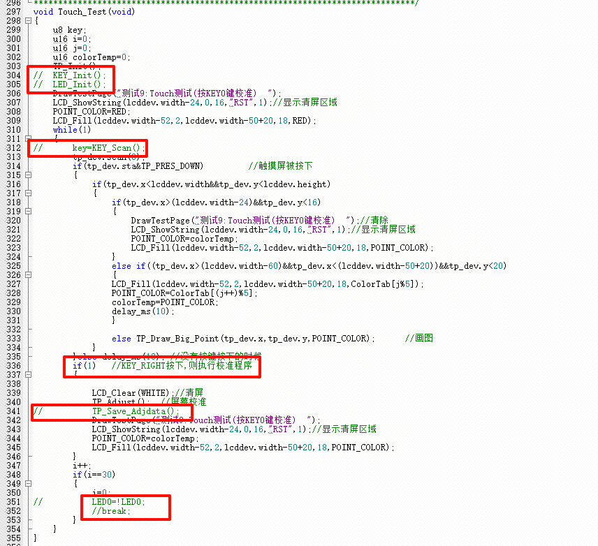
We open the test.c file to make some modifications: find the void Touch_Test(void); function, comment out some statements inside, and change the key==1 in line 282 to 1.
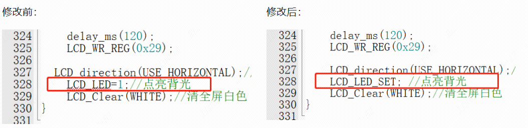
- Open the lcd.c file and find the void LCD_Init(void); function, replace LCD_LED=1; with LCD_LED_SET;
Open the touch.h file and change part of the code to the following:
#define PEN GPIO_ReadPin(PORT_LCD_PEN,GPIO_LCD_PEN) //INT#define DOUT GPIO_ReadPin(PORT_LCD_TD0,GPIO_LCD_TD0) //MISO#define TDIN(x) GPIO_WritePin(PORT_LCD_TDIN,GPIO_LCD_TDIN,x?GPIO_Pin_SET:GPIO_Pin_RESET) //MOSI#define TCLK(x) GPIO_WritePin(PORT_LCD_TCLK,GPIO_LCD_TCLK,x?GPIO_Pin_SET:GPIO_Pin_RESET) //SCLK#define TCS(x) GPIO_WritePin(PORT_LCD_CS2, GPIO_LCD_CS2, x?GPIO_Pin_SET:GPIO_Pin_RESET) //CS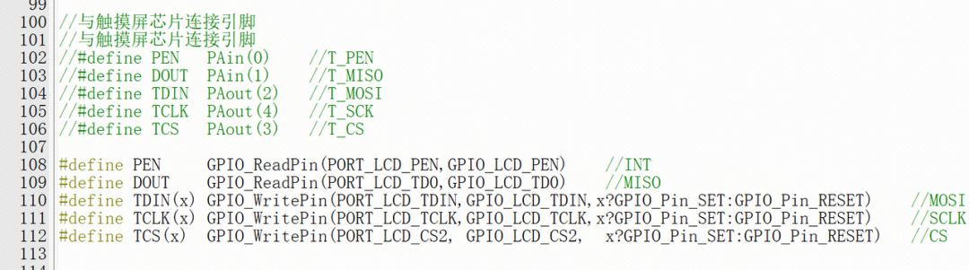
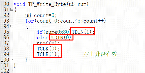
Then we open the touch.c file and replace the following statements:
TCLK = 1; -----replace with------> TCLK(1);TCLK = 0; -----replace with------> TCLK(0);
TDIN = 1; -----replace with------> TDIN(1);TDIN = 0; -----replace with------> TDIN(0);
TCS = 1; -----replace with------> TCS(1);TCS = 0; -----replace with------> TCS(0);
For example:
At this point, the porting is complete. Please proceed to section 4 for porting verification.
4Porting Verification>>>Enter the following code in main.c
/* * Change Logs: * Date Author Notes * 2024-06-18 LCKFB-LP first version */#include "board.h"#include "stdio.h"#include "bsp_uart.h"#include "Lcd.h"#include "gui.h"#include "test.h"#include "spi.h"#include "touch.h"int32_t main(void){ board_init(); // Development board initialization uart1_init(115200); // Serial port 1 baud rate 115200 LCD_Init(); // LCD screen initialization while(1) { main_test(); // Test main interface Test_Color(); // Simple screen fill test Test_FillRec(); // GUI rectangle drawing test Test_Circle(); // GUI circle drawing test Test_Triangle(); // GUI triangle drawing test English_Font_test(); // English font example test Chinese_Font_test(); // Chinese font example test Pic_test(); // Image display example test Rotate_Test(); // Rotation display test // If not using touch, or if touch functionality is not needed, please comment out the following touch screen test item Touch_Test(); // Touch screen handwriting test }}Power-on effect:
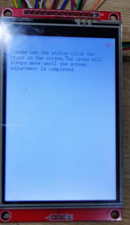
Successful Module Porting Case (Software SPI):
Link:https://pan.baidu.com/s/1fVFssmnIdNbN4F0ZdxpwlQ?pwd=LCKF
Extraction Code: LCKF
ENDPrevious ReviewsREVIEW
[Product Application] CW32 Electric Tool Product Open Source
[Product Solution] Low-Cost Electric Tool Solution Based on CW32L010
[Product Application] Smart Power Bank Based on CW32 (Solution Open Source)
[Product Application] CW-W88 General Control Board Design Scheme (Open Source)
[Product Application] Angle Grinder Controller Product Solution Based on CW32
[Product Solution] Low-Voltage Brushless Fan Sensorless Controller Based on CW32F030C8
[Product Solution] Brushless DC Hollow Cup Motor Sensor Control Drive Solution Based on CW32
[Product Solution] Brushless DC Hollow Cup Motor Sensorless Square Wave Control Drive Solution Based on CW32
[Product Solution] Digital Voltage and Current Meter Product Solution Based on CW32F003E4P7
[Product Solution] CW32L010 Low-Cost Industrial Instrument
CW32 Ecological Community (WX) Group
 Scan to Join QQ GroupGroup 4| 478586307
Get materials and“Developer Support Plan”First-hand information