1.Device Control
This section mainly describes how the master controls the driver through the CANopen bus, such as turning the servo ON or clearing alarms.
(1)Control State Machine
The master controls the driver through the control word, and by reading the driver’s status word, it can know the current state of the driver. This section will use the following terms:
State(State): If the main power is activated or an alarm occurs, the servo driver is in different states. The state machine under CANopen bus control will be emphasized in this section.
For example: SWITCH_ON_DISABLED
StateTransition(State Transition): The state machine also defines how to transition from one state to another. State transitions rely on the control word controlled by the master or the driver itself, for example, when the driver has an alarm.
Command(Command): To initiate a State Transition, the bit combinations of the control word are defined, and these bit combinations are called Commands.
Statediagram(State Diagram): All States and State Transitions together form the State Diagram.
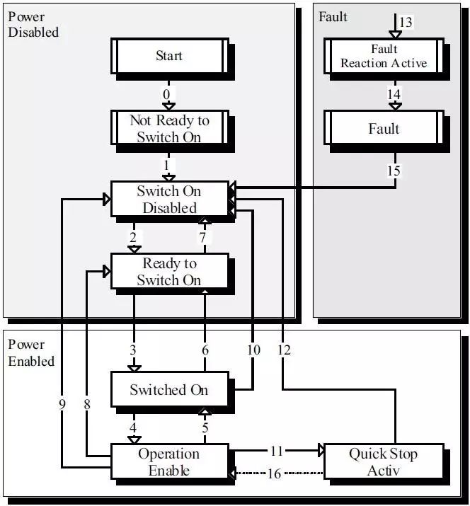
As shown in the figure above, the state machine can be divided into three parts: “Power Disabled” (main power off), “Power Enabled” (main power on), and “Fault”. All states enter “Fault” after an alarm occurs. After powering on, the driver completes initialization and then enters the SWITCH_ON_DISABLED state. In this state, CAN communication can be performed, and the driver can be configured (for example, setting the driver’s operating mode to “PP” mode). At this time, the main power is still off, and the motor is not excited. After State Transition 2, 3, and 4, it enters OPERATION ENABLE. At this point, the main power is on, and the driver controls the motor according to the configured operating mode. Therefore, before this state, it must be confirmed that the driver’s parameters and corresponding input values are correctly configured to zero. State Transition 9 completes the shutdown of the main circuit. Once the driver has an alarm, the driver’s state enters FAULT.
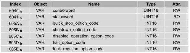
(2)Device Control Related Parameters
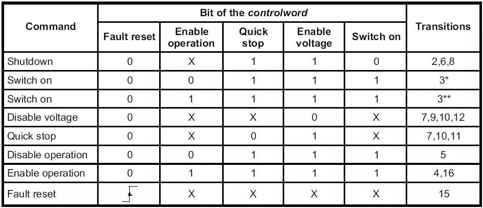
The control word bit description is shown in the figure below

Bit0~ 3 and Bit7:
The transmission of the state machine is triggered by the corresponding control command composed of these 5 bits.
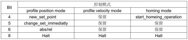
Bit4, 5, 6, 8:
These 4 bits are defined differently under different control modes.
The status word bit description is shown in the figure below
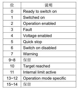
Bit0~ 3 , Bit5 and Bit6:
The combination of these bits indicates the state of the driver.
Bit4: Voltage enabled
When this bit is 1, it indicates that the main power is on.
Bit5: Quick stop
When this bit is 0, it indicates that the driver will stop according to the settings (605A h:quick_stop_option_code).
Bit7: Warning
When this bit is 1, it indicates that the driver has detected an alarm.
Bit10: Target reached
This bit has different meanings under different control modes.
In Profile Position Mode, when the set position is reached, this bit will be set; when Halt is initiated and the speed slows to zero, this bit will be set; when a new position is set, this bit will be cleared.
In Profile Velocity Mode, when the speed reaches the given speed, this bit will be set; when Halt is initiated and the speed slows to zero, this bit will be set.
Bit11: Internal limit active
When this bit is 1, it indicates that the internal torque exceeds the set value.
shutdown_option_code
When the Operation Enable → Ready to Switch On state transition occurs, shutdown_option_code determines how to stop 
disable_operation_option_code
When the Operation Enable → Switched On state transition occurs, disable_operation_option_code determines how to stop.
 quick_stop_option_code
When the Operation Enable → Quick Reaction Active state transition occurs, quick_stop_option_code determines how to stop. 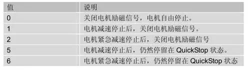
halt_option_code
When bit8 (halt) of the control word is 1, halt_option_code determines how to stop.

fault_reaction_option_code

For further introductions, please pay attention to the next WeChat update.
This article is reproduced from the shared document of: Nanjing Estun ProNet Servo Driver Manual. This manual is very well written and contains a lot of basic and practical knowledge about CANopen, so I take this opportunity to share it with everyone! Thanks to the engineers at Nanjing Estun!