Follow our public account to not miss any updates!

This tutorial was originally published by the author strongerHuang in September 2018.
Tags: CAN, CANOpen, CanFestival
Copyright: Commercial use prohibited
Disclaimer:This document is for personal learning use only. Please contact the author for authorization before reprinting.
1Introduction
The previous article discussed the important role of CAN transceivers and mentioned that the main advantage of the CAN bus lies in the CAN controller. The position of the CAN controller in the CAN network is shown in the following figure:
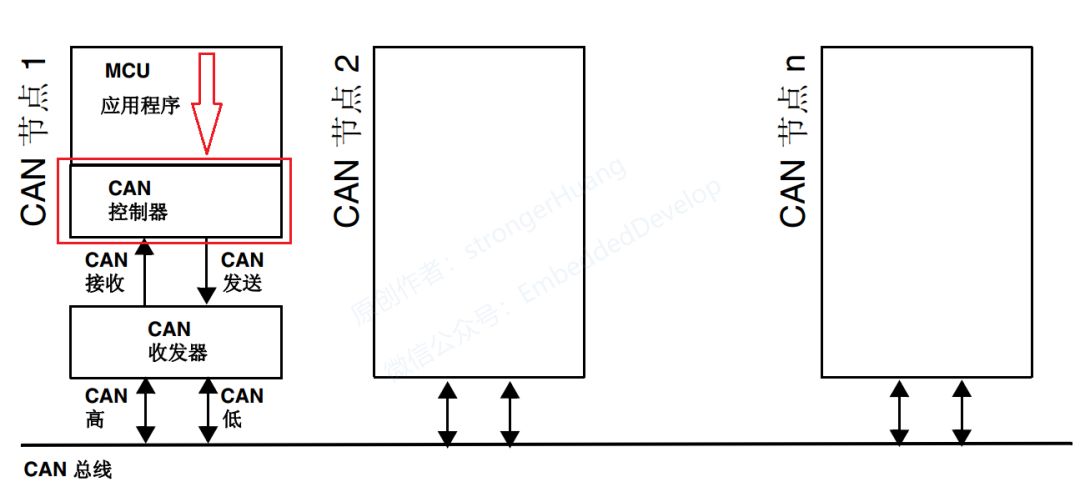
This article discusses several important functions implemented by the CAN controller: CAN bus baud rate, bit timing, and frame types.
2
CAN Bus Baud Rate
The CAN bus is a type of asynchronous communication, which means there is a communication baud rate, and this baud rate generator is located inside the CAN controller. We do not need to understand how it is generated, but we need to understand its meaning. This section discusses the following two points for beginners.
2.1 Asynchronous Communication
In serial communication, it is mainly divided into asynchronous communication and synchronous communication.
Synchronous Communication: Communication where devices use a synchronization signal (CLK clock) to achieve data transmission is called synchronous communication. In communications like I2C and SPI, there is a clock signal. In fact, USART in STM32 also has synchronous capabilities, but most people only use its asynchronous functionality.
Asynchronous Communication: Simply put, it is when communication devices send and receive data at agreed-upon times. This time determines the baud rate discussed in this section.
2.2 Baud Rate
Many engineers have not fully understood what baud rate is, so I will briefly explain its meaning in conjunction with UART baud rate.
In electronic communication, baud refers to the modulation rate, which is the rate at which the effective data signal modulates the carrier, i.e., the number of times the carrier modulation state changes per unit time. It measures the symbol transmission rate, 1 baud means transmitting 1 symbol per second.
UART transmits 240 characters per second, and each character format consists of 10 bits (1 start bit, 1 stop bit, 8 data bits), thus the baud rate is240 Bd, and the bit rate is10 bits * 240 per second = 2400 bps.
From the above description, we can summarize:
Bit Rate: The number of binary bits transmitted per unit time;
Baud Rate: The number of symbols transmitted per unit time;
Only when each symbol represents one bit of information can the baud rate equal the bit rate in numerical value, but their meanings are not the same.
3
Bit Timing
The previous section discussed baud rate, and the bit timing determines the baud rate. In the CAN standard, one bit can be divided into four segments:
-
Synchronization Segment (SS)
-
Propagation Time Segment (PTS)
-
Phase Buffer Segment 1 (PBS1)
-
Phase Buffer Segment 2 (PBS2)
These segments are composed of the smallest time unit known as Time Quantum (Tq).
One bit is divided into four segments, each segment composed of several Tq, which is called bit timing.
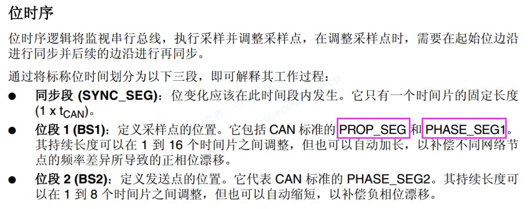
In the STM32 reference manual, bit timing is divided into three segments, but it combines the propagation segment and bit segment 1 together, as shown in the following figure:
The number of Tq that one bit consists of and how many Tq each segment contains can be set arbitrarily in bit timing. By setting the bit timing, the transmission baud rate is determined:
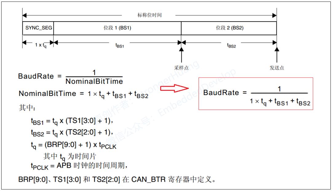
These parameters will be configured in future programming to determine the communication baud rate.
Regarding synchronization, there are hardware synchronization, re-synchronization, and other operations. However, beginners do not need to understand too much; mastering the basic content above is sufficient. More information about bit timing can be found in the ISO 11898 standard.
4
Frame Types and Format Description
The CAN bus communicates using the following five types of frames:
Data Frame: A frame used to send data from the transmitting unit to the receiving unit.
Remote Frame: A frame used by the receiving unit to request data from the transmitting unit with the same ID.
Error Frame: A frame used to notify other units of an error when one is detected.
Overload Frame: A frame used by the receiving unit to indicate it is not ready to receive.
Frame Interval: A frame used to separate data frames and remote frames from the previous frames.
Data Frames and Remote Frames have both standard and extended formats. The standard format has an 11-bit identifier ID, while the extended format has a 29-bit ID.
4.1 Data Frame
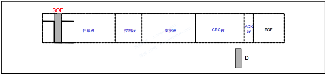
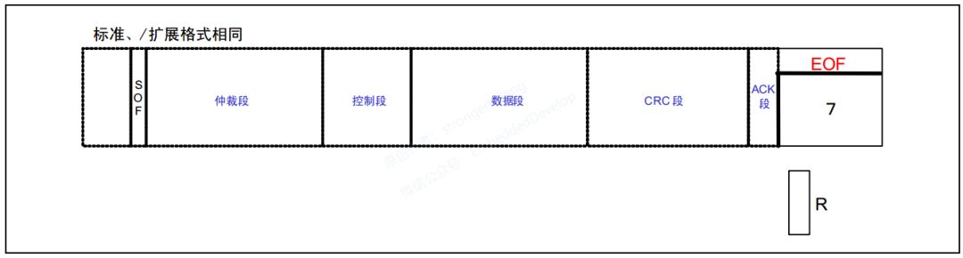
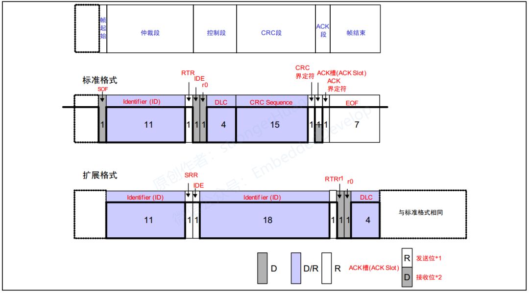
As shown in the figure, a data frame consists of seven segments:
(1) Frame Start
Indicates the segment where the data frame begins.
(2) Arbitration Segment
Indicates the segment representing the priority of the frame.
(3) Control Segment
Indicates the number of bytes of data and reserved bits.
(4) Data Segment
Contains the data, which can send 0 to 8 bytes of data.
(5) CRC Segment
Checks for transmission errors in the frame.
(6) ACK Segment
Indicates confirmation of normal reception.
(7) Frame End
Indicates the segment where the data frame ends.
To understand the meaning of a data frame, it is important to grasp its definition: a frame used to send data from the transmitting unit to the receiving unit.
In general CAN bus communication, most of the time the communication on the bus is through data frames. For example, in the CANOpen protocol, the PDO (Process Data Object) is primarily communicated using data frames.
Beginners can first understand data frames, and then the rest will be easier to comprehend. Next, we will discuss the details of the seven segments of the data frame.
4.1.1 Frame Start
The standard and extended formats are the same. It indicates the segment where the frame starts, which is a dominant bit (as shown in the figure below):
For information on dominant and recessive levels, please refer to my previous article on differential signals.
There are dominant and recessive levels on the bus.
When executing the logical “AND” on the bus, the logical value of the dominant level is “0”, and the recessive level is “1”.
“Dominant” implies “priority”; as long as one unit outputs a dominant level, the bus will be at a dominant level. Moreover, “recessive” implies “inclusiveness”; only when all units output a recessive level will the bus be at a recessive level (the dominant level is stronger than the recessive level).
4.1.2 Arbitration Segment
The structure of the standard and extended formats differs here. The arbitration segment indicates the priority of the frame, and the extended format has an additional 18-bit ID (as shown in the figure below):
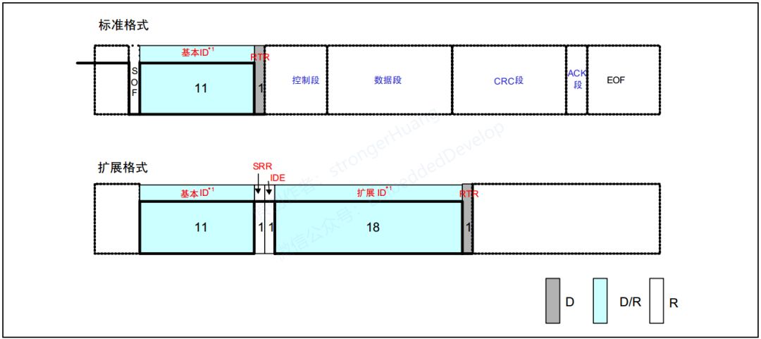
RTR = 0 represents a data frame, and RTR = 1 represents a remote frame.
The reason it is called an arbitration segment is that it uses the ID to determine which node on the bus has the right to send first. The smaller the ID (0 is dominant), the higher the priority.
4.1.3 Control Segment
The structure of the standard and extended formats differs. The control segment consists of 6 bits (as shown in the figure below):
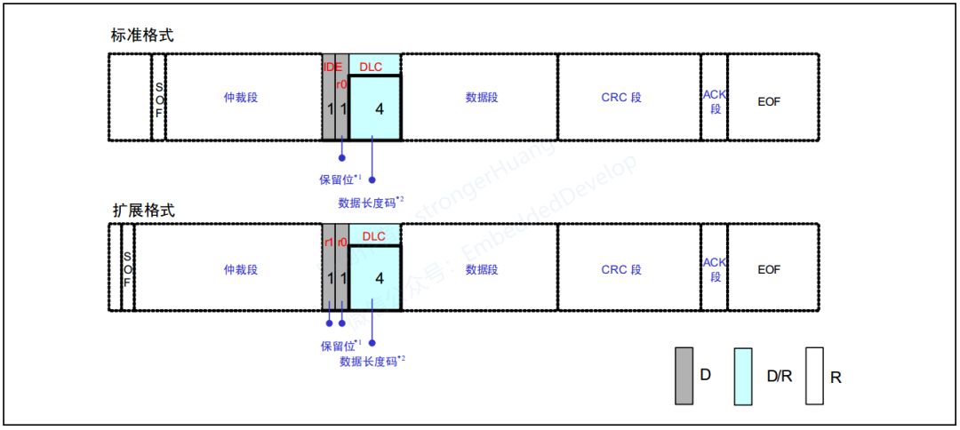
They both have 4 bits representing the Data Length Code (DLC). The standard frame has an IDE (value of 0) bit and a reserved bit r0, while the extended frame has reserved bits r0 and r1.
The reserved bits must all be sent at a dominant level. However, the receiver can receive dominant, recessive, and any combination of levels.
4.1.4 Data Segment
The standard and extended formats are the same. The data segment represents the content of the transmitted data, starting from the MSB (most significant bit), and can send 0 to 8 bytes of data, with the length determined by the previous control segment.
4.1.5 CRC Segment
The standard and extended formats are the same. The CRC segment checks for transmission errors in the frame, consisting of a 15-bit CRC sequence and a 1-bit CRC delimiter (for separation).
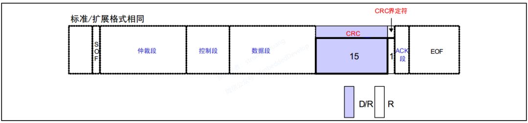
Compared to communication like RS485, the CAN controller has already performed CRC verification, so there is no need for your program to calculate it again, saving processor resources.
4.1.6 ACK Segment
The standard and extended formats are the same. The ACK segment is used to confirm whether the message was received normally. It consists of the ACK slot and the ACK delimiter.
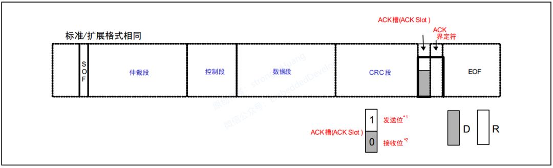
A.The transmitting unit sends 2 recessive bits in the ACK segment.
B.The unit that receives the correct message sends a dominant bit in the ACK slot, notifying the transmitting unit that the message has been received normally. This is called “sending ACK” or “returning ACK”.
4.1.7 Frame End
The standard and extended formats are the same. The frame end indicates the segment where the frame ends, consisting of 7 recessive bits.

4.2 Remote Frame
Compared to the data frame, the remote frame is used by the receiving unit to request the sending unit to send data. Therefore, the remote frame does not have a data segment. Thus, the remote frame consists of the following 6 segments:
(1) Frame Start (SOF)
Indicates the segment where the frame starts.
(2) Arbitration Segment
Indicates the segment representing the priority of the frame. It can request a data frame with the same ID.
(3) Control Segment
Indicates the number of bytes of data and reserved bits.
(4) CRC Segment
Checks for transmission errors in the frame.
(5) ACK Segment
Indicates confirmation of normal reception.
(6) Frame End
Indicates the segment where the remote frame ends.
The contents of these 6 segments are basically the same as those of the data frame, so I will not elaborate on them. Let’s discuss the differences between the remote frame and the data frame:
-
The RTR bit of the remote frame is a recessive bit, and it has no data segment.
-
The absence of a data segment in the data frame and remote frame can be distinguished by the RTR bit.
Question 1: How is the data length code represented in the remote frame, which has no data segment?
The data length code of the remote frame is represented by the data length code of the requested data frame.
Question 2: What is the purpose of a data frame without a data segment?
For example, it can be used for periodic connection confirmations/responses among units, or when the arbitration segment itself carries substantial information.
4.3 Error Frame
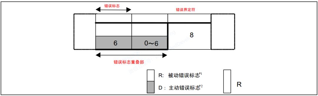
Used to detect errors during the reception and transmission of messages and to notify of errors. The error frame consists of an error flag and an error delimiter.
(1) Error Flag
The error flag includes both active error flags and passive error flags.
-
Active Error Flag: 6 dominant bits.
-
Passive Error Flag: 6 recessive bits.
(2) Error Delimiter
The error delimiter consists of 8 recessive bits.
4.4 Overload Frame
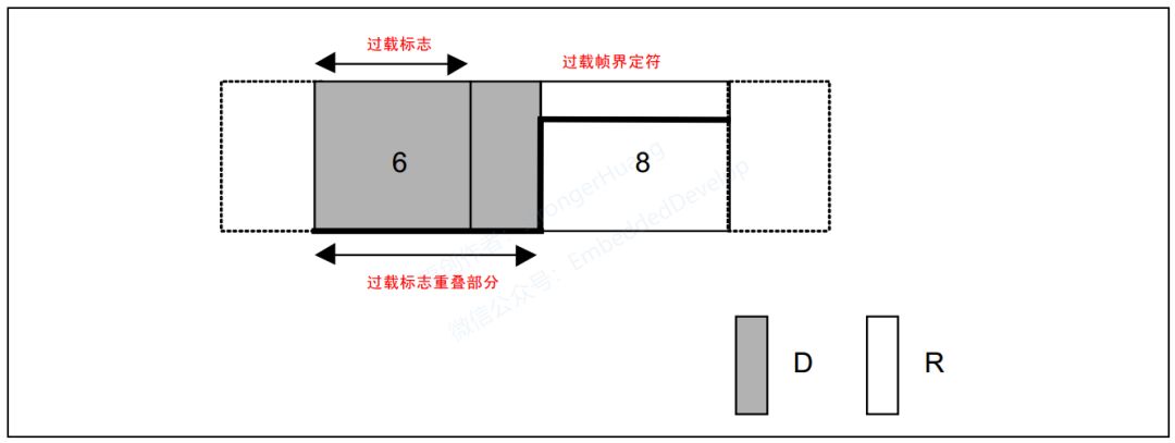
The overload frame is used to notify that the receiving unit is not yet ready to receive. The overload frame consists of an overload flag and an overload delimiter.
(1) Overload Flag
6 dominant bits.
The structure of the overload flag is the same as that of the active error flag.
(2) Overload Delimiter
8 recessive bits.
The structure of the overload delimiter is the same as that of the error delimiter.
4.5 Frame Interval
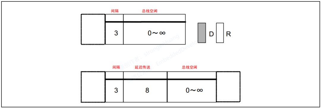
The frame interval is used to separate data frames and remote frames. Data frames and remote frames can be separated from any previous frame (data frame, remote frame, error frame, overload frame) by inserting a frame interval.
No frame interval can be inserted before overload frames and error frames.
(1) Interval
3 recessive bits.
(2) Bus Idle
Recessive level, with no length limit (0 is also acceptable).
In this state, the bus can be considered idle, and units wishing to send can start accessing the bus.
(3) Delayed Transmission (Transmission Temporarily Stopped)
8 recessive bits.
This segment is included only in the frame interval after a unit in the passive error state has just sent a message.
5
Notes
1. Some images and texts in this document are sourced from the internet and are for personal learning use only. All rights reserved, commercial use is prohibited.
2. This article was edited and organized by me alone, so there may be some errors.
3. This article is included in the public account “strongerHuang”. Follow the public account and reply with 【CANOpen Series Tutorial】 to view the entire series of tutorials.
6Conclusion
If you find this article helpful, remember to give me a thumbs up and share it. (Likes are the motivation for the author to update articles)
Scan the QR code below and follow us for more exciting content in the bottom menu!

Long press to recognize the QR code in the image to follow

Appreciation is recognition and support for the author!