Click on the top “Baijian Technology”, to pin the public account
Embedded technical content delivered promptly
——
Author: linuxdrivers
Original article:
https://blog.csdn.net/linuxdrivers/article/details/5917478
In the previous article, “An Overview of Linux PCI Device Drivers (Part 1)” (hereafter referred to as Overview (1)), we introduced the PCI configuration register set, and Linux PCI initialization utilizes these registers. Later, we will provide an example to illustrate the main tasks of Linux PCI device drivers (not all tasks); this will only be a textual introduction without delving into specific code analysis, as analyzing the code would essentially involve interpreting Chapter 8 of the book “Analysis of the Linux Kernel Source Code (Volume 2)”. Readers interested in code analysis can refer to that book, and we will not delve deeper into the code here.
The Linux PCI device driver code must scan all PCI buses in the system to find all PCI devices (including PCI-PCI bridge devices). Each PCI bus in the system has a number, with the root PCI bus numbered as 0. All root buses currently present in the system (as there may be more than one Host/PCI bridge, leading to multiple root buses) are linked into a global root bus linked list through the node member in their pci_bus structure, with the head described by a global variable of type struct list_head named pci_root_buses. We can see the following definition in /linux-2.4.18/linux/drivers/pci/pci.c at line 38:
LIST_HEAD(pci_root_buses);
All subordinate buses under the root bus are linked to their parent bus’s children list through the node member in their pci_bus structure. Thus, through these two PCI bus linked lists, the Linux kernel organizes all pci_bus structures in an inverted tree manner.
Additionally, each PCI device is represented by a pci_dev structure, and each pci_dev structure is concurrently linked into two queues. On one hand, it is linked into a global pci_dev structure queue through its member global_list (the queue head is pci_devices); simultaneously, it is also linked into the pci_dev structure queue devices of the bus it resides in through its member bus_list (the queue head is pci_bus.devices, which is the devices queue of the PCI bus where this PCI device is located), and its pointer bus (the bus member in the pci_dev structure) points to the pci_bus structure representing its bus.
If the specific device is a PCI-PCI bridge, its pointer subordinate must also point to the pci_bus structure representing another PCI bus. Similarly, we can see the following definition in /linux-2.4.18/linux/drivers/pci/pci.c at line 39:
LIST_HEAD(pci_devices);
For the PCI device linked list, we can understand it through Figure 1.
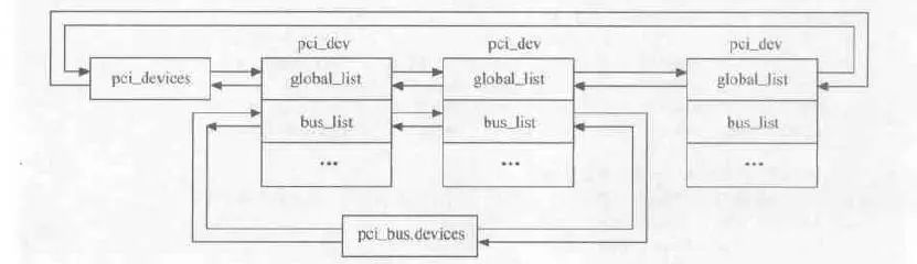
Figure 1 Linux PCI Device Linked List
Note: This figure is excerpted from Chapter 21 of “Detailed Explanation of Linux Device Driver Development”.
Regarding the PCI system structure diagram posted in Overview (1), the corresponding data structures in the Linux kernel are shown in Figure 2.
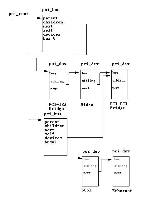
Figure 2 Linux Kernel PCI Data Structures
The Linux PCI initialization code starts scanning from PCI bus 0. It attempts to discover each device in the slots by reading the “Vendor ID” and “Device ID”. If a PCI-PCI bridge is found, a pci_bus data structure is created and linked into the tree formed by the pci_bus and pci_dev data structures pointed to by pci_root_buses. The PCI initialization code determines whether a PCI device is a PCI-PCI bridge by checking the device class code 0x060400.
Then, the Linux core begins constructing the PCI bus and devices on the other end of this bridge device. If another bridge device is found, the same steps are followed to continue the construction. This process is referred to as a depth-first algorithm. The PCI-PCI bridge spans between two buses, and the contents of the registers PCI_PRIMARY_BUS and PCI_SECONDARY_BUS indicate the bus numbers at its two ends, where PCI_SECONDARY_BUS is the bus that the PCI-PCI bridge connects to and controls, while PCI_SUBORDINATE_BUS indicates the highest bus number in the subtree rooted at this bridge.
We can see the following definition in /linux-2.4.18/linux/include/linux/pci.h:
112:  /* Header type 1 (PCI-to-PCI bridges) */

113:  #define PCI_PRIMARY_BUS           0x18       /* Primary bus number */

114:  #define PCI_SECONDARY_BUS     0x19       /* Secondary bus number */

115:  #define PCI_SUBORDINATE_BUS  0x1a       /* Highest bus number behind the bridge */
Since a depth-first scan is performed during the enumeration phase, the bus numbers in the subtree are always continuously incremented. When the CPU writes a composite address into the I/O register 0xCF8, starting from bus 0, each PCI-PCI bridge compares the composite address’s bus number with its own bus number; if they match, it uses the logical device number to search for the target device on that bus;
If not, it further compares this bus number with the content of PCI_SUBORDINATE_BUS. If the target bus number falls within the current subtree range, it passes the composite address to the downstream PCI-PCI bridges; otherwise, it ignores it. Thus, the target device will ultimately be found. Of course, this process only needs to occur during the configuration phase of PCI devices; once configured, the CPU accesses the target device directly through the relevant bus address.
For a PCI-PCI bridge to correctly pass read and write requests for PCI I/O, PCI Memory, or PCI Configuration address spaces, it must know the following information:
(1) Primary Bus Number
The PCI bus where this PCI-PCI bridge resides is called the primary bus.
(2) Secondary Bus Number
The PCI bus connected to this PCI-PCI bridge is called the secondary bus/sub bus number.
(3) Subordinate Bus Number
The maximum bus number of the subordinate PCI buses. This can be a bit convoluted, but the following analysis will clarify it.
PCI I/O and PCI Memory Windows
The configuration registers of a PCI bridge differ from those of general PCI devices. General PCI devices can have six address ranges plus one ROM range, representing the actual memory or register ranges present on the device. However, a PCI bridge may not necessarily have memory or register ranges but has three address filtering ranges. Each address filtering range determines an address window; if an address sent from the CPU falls within a certain window of the PCI bridge, it can pass through the PCI bridge to reach the connected bus.
Additionally, the command register of the PCI bridge contains two control bits called “memory access enable” and “I/O access enable”. When both control bits are 0, all these windows are closed. Before the initialization of the PCI bus is complete and appropriate bus addresses are assigned to the various ranges on the PCI devices, it is precisely because these two control bits are 0 that there is no interference to the CPU side. For example, in the PCI system schematic from Overview (1), only when the PCI I/O or PCI memory address in read and write requests belongs to SCSI or Ethernet devices will the PCI-PCI bridge forward these requests from PCI bus 0 to PCI bus 1. This filtering mechanism can prevent unnecessary proliferation of addresses in the system.
To achieve this, each PCI-PCI bridge must be correctly set up with its starting address and size for PCI I/O or PCI memory. When a read or write request address falls within its responsible range, this request will be mapped to the secondary PCI bus. Once the PCI-PCI bridges in the system are set up, if the PCI I/O and PCI memory addresses accessed by the device driver in Linux fall within these windows, then these PCI-PCI bridges are transparent. This is a very important feature that makes the work of Linux PCI device driver developers easier.
The issue is that when configuring a PCI-PCI bridge, the subordinate bus number of this PCI-PCI bridge is not known. Therefore, it is unclear whether there are other PCI-PCI bridges below this PCI bridge. Even if you know, it is unclear how to assign values to them. The solution is to utilize the aforementioned depth scanning algorithm to scan each bus. Whenever a PCI-PCI bridge is found, assign values to it.
When a PCI-PCI bridge is discovered, its secondary bus number can be determined. We temporarily assign its subordinate bus number a value of 0xFF. Next, we begin scanning the downstream bridges of this PCI-PCI bridge. This process may seem a bit complex, but the example below will provide a clear explanation:
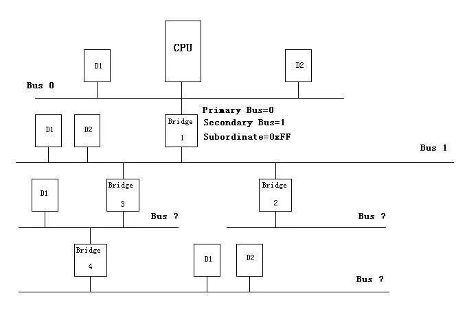
Figure 3, Configuring the PCI System – Step One
PCI-PCI Bridge Numbering — Step One
Using the topology in Figure 3 as an example, the first bridge discovered during scanning is Bridge 1. The downstream PCI bus number of Bridge 1 is assigned a value of 1. Naturally, the secondary bus number of this bridge is also 1. Its subordinate bus number is temporarily assigned a value of 0xFF. The above assignment means that all type 1 PCI configuration addresses with bus numbers 1 or higher (<255) will be passed to PCI bus 1 by Bridge 1.
If the PCI bus number is 1, Bridge 1 is also responsible for converting the configuration address type to type 0 (for the types 0 and 1 mentioned here, please refer to Overview (1)). Otherwise, no conversion is performed. The above action is the configuration work performed by the Linux PCI initialization code for bus 0 when it starts scanning bus 1.
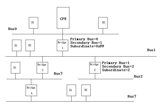
Figure 4, Configuring the PCI System – Step Two
PCI-PCI Bridge Numbering — Step Two
Since the Linux PCI device driver uses a depth-first algorithm for scanning, the initialization code begins scanning bus 1. As a result, Bridge 2 is discovered. Since no other PCI-PCI bridges are found beneath Bridge 2, its subordinate bus number is 2, equal to its secondary bus number. Figure 4 shows the assignment status of buses and PCI-PCI bridges at this moment.
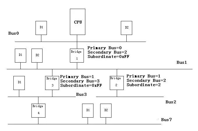
Figure 5, Configuring the PCI System – Step Three
PCI-PCI Bridge Numbering — Step Three
The Linux PCI device driver code returns from scanning bus 2 to continue scanning bus 1, discovering Bridge 3. Its primary bus number is assigned a value of 1, and its secondary bus number is 3. Since another PCI-PCI bridge is found on bus 3, the subordinate bus number of Bridge 3 is temporarily assigned a value of 0xFF. Figure 5 shows the configuration status of the system at this moment. So far, the type 1 PCI configurations with bus numbers 1, 2, and 3 can be correctly transmitted to the corresponding buses.
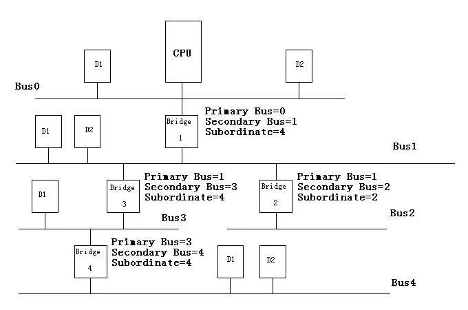
Figure 6, Configuring the PCI System – Step Four
PCI-PCI Bridge Numbering — Step Four
Now Linux begins scanning PCI bus 3, the downstream of Bridge 3. There is another PCI-PCI bridge on PCI bus 3, Bridge 4. Therefore, the primary bus number of Bridge 4 is set to 3, and the secondary bus number is set to 4. Since there are no other bridge devices beneath Bridge 4, its subordinate bus number is 4.
Then we return to PCI-PCI Bridge 3. At this point, the subordinate bus number of Bridge 3 is updated from 0xFF to 4, indicating that bus 4 is the furthest PCI-PCI bridge downstream from Bridge 3. Finally, the Linux PCI device driver code assigns the value 4 to the subordinate bus number of Bridge 1 in the same manner. Figure 6 reflects the final status of the system.
Note: The overall structure of “An Overview of Linux PCI Device Drivers (Part 2)” is as described above. I strongly recommend friends who want to learn Linux PCI device drivers to refer to Chapter 8 of “Analysis of the Linux Kernel Source Code (Volume 2)” and Chapter 21 of “Detailed Explanation of Linux Device Driver Development” for study.
-THE END-
Previous article:New Lesson 14 on und exception mode BUG and corresponding solutions
There is a line
Promotion
Linux versions above 3.1 have supported device tree dts. If you are working on drivers or system-related tasks, it is recommended to learn about device trees, which will definitely be useful. Here, I recommend a video recorded by Teacher Wei over three months, consisting of 6 lessons and 29 sections, lasting about 10 hours. The same content is sold by peers for over 399, but we still offer it at a fair price of 69. Feel free to inquire.
Highlights of the device tree video:
1. Fair price, detailed explanation, truly thorough on device trees
2. Continuation of the consistent style: explaining while drawing, coding on-site
3. Rich content covering u-boot/kernel/driver handling of device trees
dts=>dtb=>device_node=>platform_device
Purchase link:
https://item.taobao.com/item.htm?spm=a1z10.1-c-s.w5003-18996326770.1.764a82accZHBAf&id=577749510933&scene=taobao_shop
If you have concerns, please try first:
Traditional writing of character device drivers▲
What if I just want to use the device tree without delving into it? ▲
Below are some evaluations from device tree students▼

How to obtain the selected technical articles from this public account?
Please reply “m” in the public account backend to get it
Join the community:
The official WeChat group of Wei Dongshan is open for students to communicate. Add the administrator’s WeChat (13266630429, verify: join group) to join, with limited spots available on a first-come, first-served basis.

If you like it, please click [ Like ]