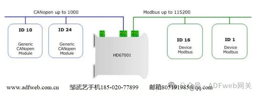
CANopen / Modbus Master – HD67001 Converter
Author: Zou Wuyi Mobile 185-020-77899 Email [email protected]
Configuration Description: The “CANopen/Modbus Master– Converter“ allows communication between the CANopen network and the Modbus network. You need to install Compositor SW67001 software on your computer to perform the following operations:
- Define the CANopen frames read from Modbus;
- Define the CANopen frames written to Modbus.
1. When starting SW67001, the right window appears (Figure 4):
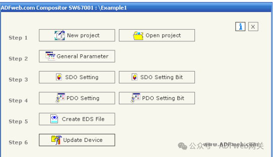
2. New Project / Open Project: The “ New Project“ button will create a folder containing the entire device configuration. Device configurations can also be imported and exported:
- To clone the programmable CANopen to Modbus gateway configuration for configuring another device in the same way, the folder and all its contents must be retained;
- To clone a project for a different version of that project, simply copy and rename the project folder, then use “ Open Project“ button to open the new folder;
- When creating a new project or opening an existing project, you will have access to various configuration sections of the software:
- Set communication;
- SDO settings;
- PDO settings.
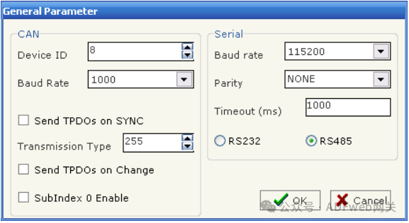
3. General Parameters: This section defines the basic communication parameters for the two buses (CANopen and Modbus). By pressing the “ General Parameters“ button from the SW67001 main window (Figure 4), the “ General Parameters“ window (Figure 5) will appear.
- In the “ Device ID” field, define the CANopen address;
- In the “ Baud Rate“ field, define the communication rate for both buses;
- “ Send TPDO on SYNC, if this option is selected, the device will send PDO when there is a SYNC command on the network;
- “ Transmission Type“ field defines the transmission type of PDO;
- “ Send TPDO on State Change“. Allows automatic sending of TPDO when the state of the TPDO variable changes;
- In the “ Parity“ field, define the serial parity;
- “ Timeout“ is the maximum time the device waits for a response from the queried slave;
- Data bits and stop bits are serial parameters, defaulting to 8 and 1 respectively;
- The gateway has two optional interfaces on the Modbus side: RS485 or RS232. Choose the desired option.
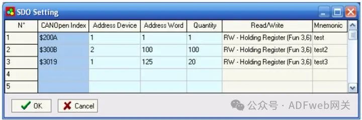
4. SDO Settings: In the “SDO Settings“ section, the following objects can be defined:
- CANopen SDO can access a word ModBUS. By pressing the “SDO Settings“ button from the SW67001 main window (Figure 4), the “SDO Settings“ window (Figure 6) will appear. In the right scene:
- In the “CANOpen Index“ field, insert the index of CANopen SDO;
- In the “ Device Address“ field, insert the address of the Modbus device containing Modbus data;
- In the “ Word Address“ field, insert the register address containing Modbus data;
- In the “ Quantity“ field, insert the number of consecutive words you configured;
- In the “ Read/Write“ field, define whether the SDO is read or write;
- In the “ Mnemonic“ field, define the description.
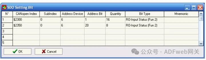
5. SDO Setting Bits In the “SDO Setting Bits“ section, the following objects can be defined:
- CANopen SDO (Service Data Object) is used to access ModBUS bits (status).
By pressing the “SDO Setting Bits“ button from the SW67001 main window (Figure 4), the “SDO Setting Bits“ window (Figure 7) will appear.
In the above scene:
- In the “CANOpen Index“ field, input the index of CANopen SDO;
- In the “ Subindex“ field, input the subindex (recommended to always be 0);
- In the “ Device Address“ field, input the address of the device containing Modbus bits;
- In the “ Bit Address“ field, input the address of the bit you wish to read or write;
- In the “ Quantity“ field, input the number of consecutive bits you configured;
- In the “ Bit Type“ field, define the type of bit;
- In the “ Mnemonic“ field, you can insert a brief description.
Each SDO can read up to 16 bits (4 bytes: the last 2 bytes are always set to 0).
Data:0001 0001 0011 1111Mask:0011 0110 1111 1111Bits Written:xx01 x00x 0011 1111 (bits marked with x indicate not written).
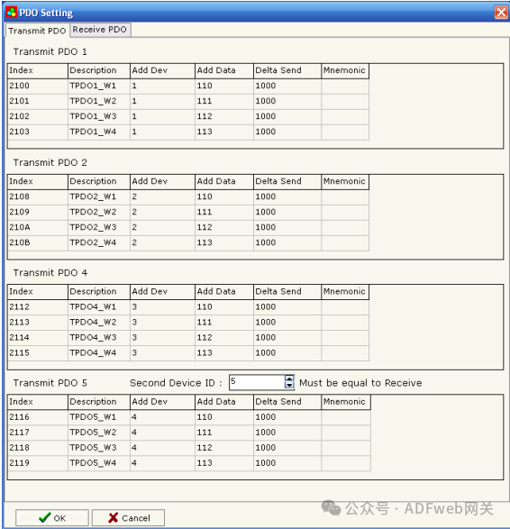
6. PDO Settings: The gateway allows the use of 4 receiving PDOs and 4 sending PDOs. All PDOs are mapped to specific objects, such as TPDO1 (2100,2101,2102,2103). One PDO has a length of 8 bytes, divided into 4 words. Each word is associated with a word on the serial bus. When writing to the gateway’s RPDO, the data will be written to a specific address of the serial device. When requesting TPDO, the PDO will contain data read from a specific device and address on the serial bus.
By pressing the “PDO Settings“ button in the SW67001 main window (Figure 4), the “PDO Settings“ window (Figure 8) will appear. In the right scene:
- “ Index“ field is filled and cannot be modified;
- “ Description“ field is filled and cannot be modified;
- In the “ Add Device“ field, insert the address of the Modbus device;
- In the “ Add Data“ field, insert the address of the Modbus register;
- In the “Delta Send“ field, insert the Delta send range (when at least one Modbus word exceeds ±Delta send range, the corresponding TPDO will be transmitted automatically);
- In the “ Mnemonic“ field, you can insert a brief description;
- In the second device ID field, insert the device ID of PDO5. If your device ID is 8 (see “ General Parameters“ section), then the COB ID is as follows: TPDO1 = 180 + Device ID = 188 TPDO2 = 280 + Device ID = 288 TPDO4 = 480 + Device ID = 488 TPDO5 = 180 + Second Device ID = 184.
For the same reason, there is also a second device ID on the receiving PDO. When inserting the second device ID, do not insert a device ID that already exists in the network.
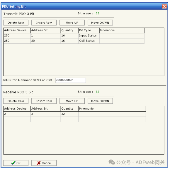
7. PDO Setting Bits The gateway allows the use of 1 digital receiving PDO and 1 digital sending PDO. TPDO3 maps to address 2110, RPDO3 maps to address 2111. One PDO has a length of 8 bytes. When writing data to the gateway’s RPDO, the data will be written to a specific address of the serial device. When requesting TPDO, the PDO will contain data read from a specific device and address on the serial bus. By pressing the “PDO Setting Bits“ button in the SW67001 main window (Figure 4), the “PDO Setting Bits“ window (Figure 9) will appear.
In the correct scene:
- In the “ Device Address“ field, input the address of the device containing the bits;
- In the “ Bit Address“ field, input the address of the bit you wish to read;
- In the “ Quantity“ field, input the number of consecutive bits you configured;
- In the “ Bit Type“ field, define the type of bit;
- In the “ Mnemonic“ field, you can insert a brief description;
- In the “PDO Auto Send Mask“ field, insert a mask.
Data:0001 0001 0011 1111 0001 0001 0011 1111 Mask:0011 0110 1111 1111 0011 1110 1110 1111 Bits Written:xx01 x00x 0011 1111 xx01 000x 001x 1111 (bits marked with x indicate not written bits)
For TPDO, the protocol converter can read up to 64 bits (8 data bytes). For RPDO, up to 32 bits can be written to the protocol converter (8 bytes:4 data bytes + 4 mask bytes).
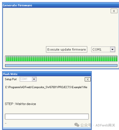
8. Update Device: In the “Update Device“ section: Insert the boot jumper (see Figure 2). To load these parameters after setting them, the communication port used for updating must be set, and the “ Execute Firmware Update“ button must be clicked on the main window.