1、CANopen in the ISO Layer Structure
From the perspective of the OSI 7-layer network model, the CAN (Controller Area Network) fieldbus only defines the 1st layer (Physical Layer, see ISO11898-2 standard) and the 2nd layer (Data Link Layer, see ISO11898-1 standard); in actual design, these two layers are entirely implemented by hardware, and designers do not need to develop related software or firmware, as they only need to understand how to call the relevant interfaces and registers to control the CAN. As shown in the figure.
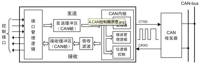
CAN Controller Structure
However, CAN does not specify the application layer. That is, it does not define the logic related to actual applications, such as digital input/output and analog input/output. Therefore, it is not complete for applications.
This is like turning iron ore (Physical Layer) into iron ingots (Data Link Layer), and then further processing it into cars, ships, rebar, tanks, and structural buildings for specific applications.
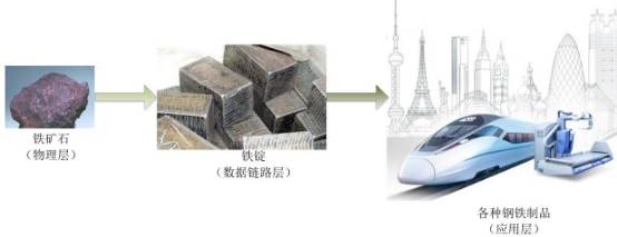
From Physical Layer to Application Layer
Therefore, almost every industry using CAN requires a higher-level protocol to define the 11/29 bit identifier and the usage of 8-byte data in the CAN message. However, in the industrial automation applications of the CAN bus, due to the increasing demand for interoperability of devices, an open and standardized higher-level protocol is needed: this protocol supports the interoperability and interchangeability of various CAN vendor devices, provides a standardized and unified system communication model in the CAN network, and offers a method for device function description and execution of network management functions. This includes:
1. Application Layer: Provides a set of useful services and protocols for each valid device in the network.
2. Communication Profile: Provides configuration for devices and the meaning of communication data, defining the data communication method.
3. Device Profile: Adds compliant behavior to device classes.
2、CANopen Protocol: Birth and Development
CANopen protocol was developed in the late 1990s by the CiA organization based in Nuremberg, Germany—CAN in Automation (http://www.can-cia.org), based on the CAL (CAN Application Layer).
CANopen and CiA
Since the founding team of the CANopen protocol is also the founding team of CAN-bus, this protocol fully leverages all the advantages of CAN-bus, especially the principle of openness, free access, and non-profit advocated by Mr. Holger Zeltwanger, the chairman of the CiA organization. Once launched, it gained widespread recognition and application in Europe. Although the CiA organization does not have strong financial backing, it has become the most popular CAN application layer protocol worldwide today. Let us remember this lovely German elder, as shown in the figure.
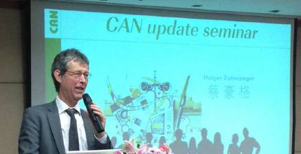
Chairman
Through multiple revisions of the CANopen protocol specification, the stability, real-time performance, and anti-interference capability of the CANopen protocol have been further improved. Moreover, the CiA organization continuously introduces device sub-protocols based on the CANopen basic protocol—CiA 301, allowing the CANopen protocol to develop and promote faster across various industries. The so-called sub-protocols refer to the redefinition of the internal data meanings of CANopen for different industry applications or the addition of new control logic.
Currently, the CANopen protocol has been widely used in motion control, vehicle industry, rail transportation, motor drives, construction machinery, and shipping industries. For example, in urban light rail vehicles (low-floor vehicles) in rail transportation, CiA collaborates with Siemens, Bombardier, and other rail transportation manufacturers to develop the following CANopen sub-protocols related to rail transportation:
CiA 421 series: Train vehicle control system
CiA 423 series: Diesel engine control system
CiA 424 series: Door control system
CiA 426 series: Exterior light control system
CiA 430 series: Auxiliary equipment control system
CiA 433 series: Interior light control system
As shown in the figure, CANopen’s position in rail vehicles is established, where the backbone network is the train bus (WTB), and each carriage uses a vehicle bus (MVB) to connect components related to train operation, which have high real-time requirements. Meanwhile, CANopen mainly connects various non-high-safety components.
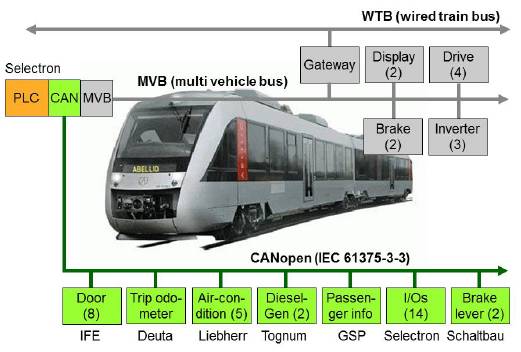
CANopen’s Application in Rail Transportation
The figure shows the structure of CANopen devices. The CANopen protocol is typically divided into three parts: user application layer, object dictionary, and communication.
The core part is the object dictionary, which describes the relationship between application objects and CANopen messages.
CANopen communication is the key part of this article, as it defines the communication rules of the CANopen protocol and the correspondence with the CAN controller driver. Familiarity with this part is crucial for a comprehensive understanding of the CANopen protocol.
The user application layer consists of application objects written by users based on actual needs. This part will not be detailed in this introductory tutorial.
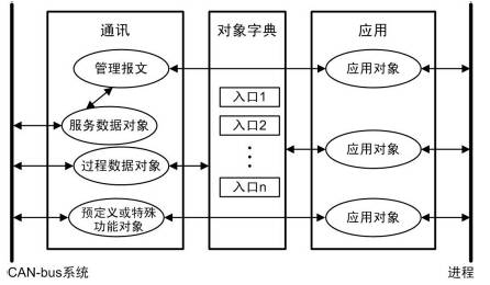
CANopen Device Structure
This article is reprinted from Guangzhou Zhiyuan (original authors Zhou Ligong, Huang Minsi)