
Welcome to join the technical exchange QQ group (2000 people): Power Electronics Technology and New Energy 739609936
High-reliability new energy industry top self-media
Here you can find power electronics, new energy content, industry development trend analysis, latest product introductions, and many technical experts sharing their experiences. Welcome to follow our WeChat public account: Power Electronics Technology and New Energy (Micro_Grid), forum: www.21micro-grid.com. The original intention of establishing this platform is for technical exchange. As a technical person interacting with products, market product information and industry technology dynamics are also essential. We hope everyone does not forget their original intentions, maintains a humble heart, and creates better products!
Power Electronics Technology and New Energy Forum
www.21micro-grid.com
The editor recommends a list of worthwhile books to read

-
Solar Microinverter
-
Comparison and Analysis of Inverter Three-Level “1” and “T” Type Circuits
-
10kVA Photovoltaic Grid-Connected Inverter Debugging Insights
-
Loop Control of Single-Phase Photovoltaic Grid-Connected Inverter
-
How to Control Leakage Current Hazards – Photovoltaic Inverter Black Technology
-
Multi-Picture Teardown Review – Opening the Case, Looking at the Red Goodway “Core


CAN bus, short for Controller Area Network, is one of the most widely used field buses internationally, and has been extensively applied in industries such as automotive manufacturing, machinery manufacturing, packaging machinery, and tobacco.
The CAN bus was developed by Bosch in Germany in the early 1980s to solve the data exchange between numerous control and testing instruments in modern automobiles. It is a multi-master bus, and the communication medium can be twisted pair, coaxial cable, or optical fiber. The communication speed can reach 1MBPS. The CAN bus communication interface integrates the physical layer and data link layer functions of the CAN protocol, and can complete the framing of communication data, including bit stuffing, data block encoding, cyclic redundancy check, priority determination, and other tasks.
A major feature of the CAN protocol is the abolition of traditional station address coding, replaced by coding the communication data blocks. This method allows for a theoretically unlimited number of nodes within the network, and the data block identifier can consist of 11 or 29 binary digits, thus defining 211 or 229 different data blocks. This data block coding method also allows different nodes to simultaneously receive the same data, which is very useful in distributed control systems. The maximum length of a data segment is 8 bytes, which meets the general requirements for control commands, working states, and testing data in the industrial field. At the same time, 8 bytes will not occupy the bus time for too long, thus ensuring the real-time nature of communication. The CAN protocol uses CRC checks and provides corresponding error handling functions, ensuring the reliability of data communication. The excellent characteristics, high reliability, and unique design of CAN make it particularly suitable for the interconnection of industrial process monitoring devices, thus receiving increasing attention from the industry and has been recognized as one of the most promising field buses.
Additionally, the CAN bus adopts a multi-master competitive bus structure, featuring multi-master operation and decentralized arbitration, as well as broadcast communication. Any node on the CAN bus can actively send information to other nodes on the network at any time without distinguishing between master and slave, thus allowing free communication between nodes. The CAN bus protocol has been certified by the International Organization for Standardization, the technology is relatively mature, and the control chips have been commercialized, offering high cost performance, particularly suitable for data communication between distributed measurement and control systems. CAN bus cards can be inserted into any PC, AT, or XT compatible machines, conveniently forming distributed monitoring systems.
CANopen is an application layer protocol based on the CAN bus. Among the open field bus standards, CANopen is one of the most famous and successful, having gained wide recognition and extensive application in Europe and the United States. In 1992, the “CAN in Automation” (CiA) association was established in Germany to begin formulating the application layer protocol CANopen for automation CAN. Since then, the association’s members have developed a series of CANopen products, which have been widely applied in fields such as machinery manufacturing, railways, vehicles, ships, pharmaceuticals, and food processing. Currently, the CANopen protocol has become a new industrial field bus standard EN-50325-4. The CANopen protocol is one of the standards defined by CAN in Automation (CiA), and in Europe, the CANopen protocol is regarded as the leading standard in industrial systems based on CAN. Most important types of devices, such as digital and analog input/output modules, drive devices, operating devices, controllers, programmable controllers, or encoders, are described in the protocol called “device description”; the “device description” defines different types of standard devices and their corresponding functions. With the support of the CANopen protocol, devices from different manufacturers can be configured via the bus.

EDS File
EDS (Electronic Data Sheet)
The EDS file describes the communication properties of devices on the CAN network (baud rate, output type, I/O provided…). It is provided by the device manufacturer for configuring nodes in configuration tools (similar to device drivers in Windows).
PDO
PDO (Process Data Object)
The CANopen frame contains I/O data
Distinguished as:
1. Transmit PDO: TXPDO carries data provided by the node to other nodes
2. Receive PDO: RXPDO is data consumed by the node
The direction of transmission is always visible from the perspective of the node. PDO does not need to contain all node mappings. Typically, analog and digital quantities are transmitted in different PDOs. The same applies to outputs!
SDO
SDO (Service Data Object)
The CANopen frame contains parameters
SDO is mainly used to read parameters from the device or write parameters to the device during program runtime
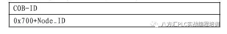
COB-ID
COB-ID (Communication Object Identifier)
Each CAN frame starts with a COB-ID, which serves as the identifier for the CAN frame.
During the configuration phase, each node, upon receiving the COB-ID, is either the provider or consumer of the frame.

Introduction
CANopen is a standard field bus protocol for industrial control systems. It is particularly suitable for real-time control PLCs, as it provides an efficient and low-cost solution for integrated and transferable industrial applications.
CANopen Protocol
The CANopen protocol is a sub-protocol based on the CAL protocol. By defining device specifications, it is even more suitable for standard industrial components. CANopen is a CIA (CAN in Automation) standard, which was rapidly promoted from the outset. In Europe, CANopen is now recognized as the industrial standard for industrial systems designed based on CAN.
Physical Layer
CAN uses differential driving on two buses (common loop). CAN signals are the voltage difference between the CAN-high and CAN-low lines.
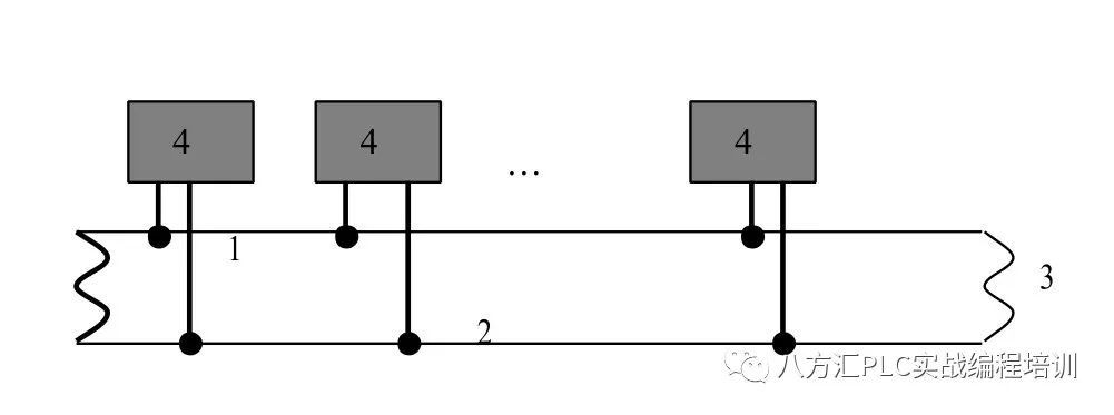
1: CAN-high line
2: CAN-low line
3: Termination resistance: 120Ω
4: Nodes
According to electromagnetic compatibility requirements, the bus can use parallel, twisted pair, or shielded wiring methods. The single-wire structure minimizes reflections.
CANopen Specification Documents
Communication specification documents
CANopen specification documents are based on “communication specification documents” to define the main communication mechanisms and their descriptions (DS301).
Device specification documents
The device specification documents describe the most important device types in the field of industrial automation and also define the types of device functions.
Examples of standard device descriptions include:
◆ Digital and analog input/output modules (DS401)
◆ Motors (DS402)
◆ Control devices (DS4P403)
◆ Closed-loop controllers (DSP404)
◆ PLC (DS405)
◆ Encoders (DS406)
Configuring Devices via CAN Bus
The possibility of configuring devices via the CAN bus is one of the basic principles required by manufacturers for autonomy.
General Specifications of CANopen Specification Documents
CANopen conforms to the following regulatory documents for CAN systems:
◆ Developed bus systems
◆ Real-time data exchange without protocol overhead
◆ Modular design with redefined dimensions
◆ Device interoperability and interchangeability
◆ Supported by numerous international manufacturers
◆ Standard network configuration
◆ Access to all parameter devices
◆ Synchronous and cyclic process data/event-driven data
CANopen Product Certification
Manufacturers providing CANopen certified products in the market are all members of the CiA organization.
CAN Standards
The CANopen protocol is defined by the CIA organization and can be accessed through their site (subject to certain restrictions): http://www.can-cia.com. Source code for master and slave devices can be obtained from various suppliers.
Communicating with the CANopen Network
The communication protocol documents are based on CAL services and protocols.
They provide users access to two types of exchanges: SDO, PDO.
When powered on, the device enters an initialization phase, followed by a pre-processing phase. During this phase, only SDO can communicate. After receiving a start command, the device enters the operational state, during which PDO communication can occur while SDO communication remains valid.
CANopen Boot-up
The boot-up process specifies a simplified boot-up program for minimal device configuration. This process is described as follows:
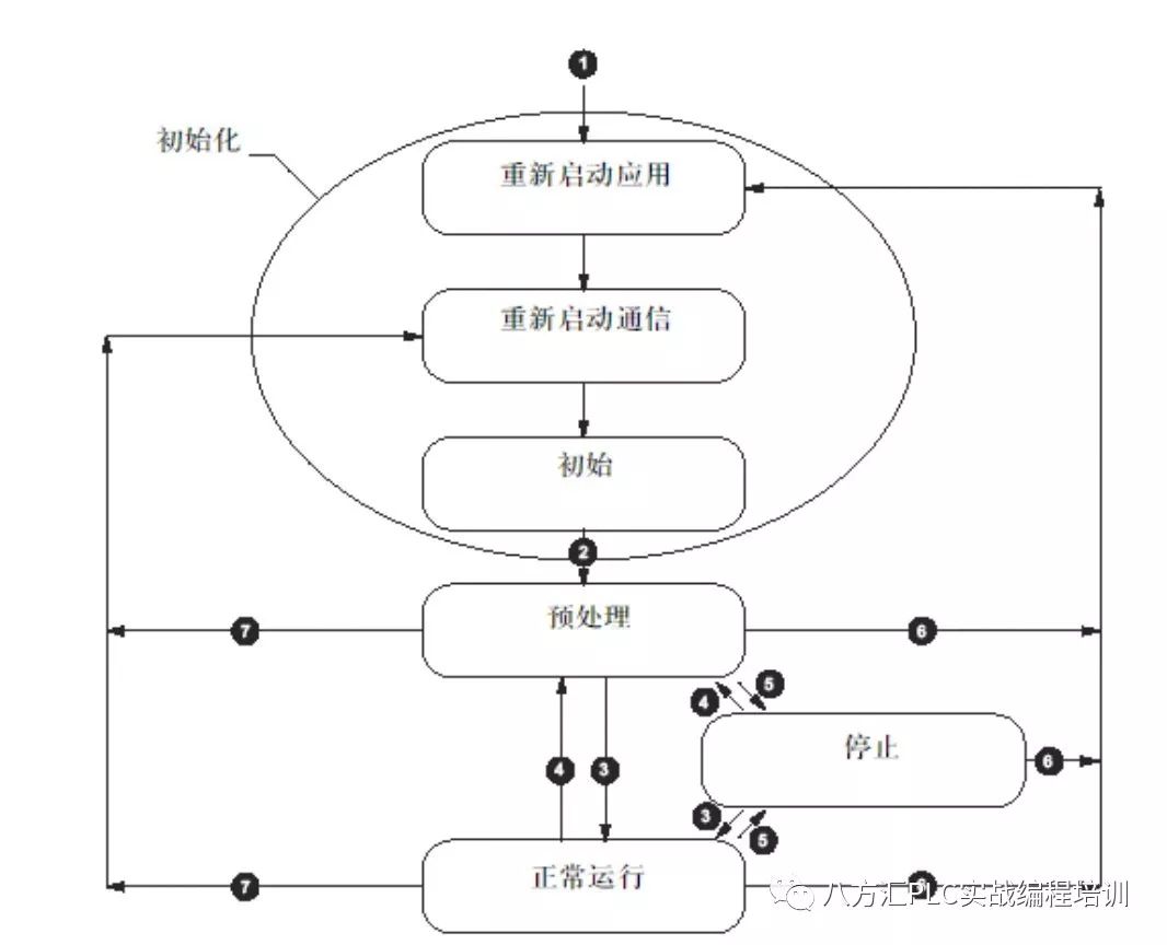
Detailed steps include:
1. Power on the module
2. Module initialization, entering pre-processing state
3. NMT service: Start remote node
4. NMT service: Pre-processing
5. NMT service: Stop remote node
6. NMT service: Restart node
7. NMT service: Restart node communication
Initial
Upon entering “restart communication,” the device enters initial mode.
The allowed operations include:
◆ Defining required communication objects (SDO, PDO, emergency event handling)
◆ Installing related CAL services
◆ Configuring the CAN controller
After initialization, the device automatically enters the pre-processing mode.
Pre-processing
Conditions for entering pre-processing:
◆ After initialization is complete
◆ In normal operating mode, upon receiving the “enter pre-processing” NMT command
In this case, the device configuration can be modified. However, only SDO can be used to read or write device parameters.
Once configuration is complete, by receiving relevant commands, the device enters the following operational states:
◆ Stop, upon receiving the “stop remote node” NMT command
◆ Run, upon receiving the “start remote node” NMT command
Stop
If the device is in “pre-processing” or “normal operating” state and receives the “node stop” command (NMT service), the device enters the “stop state”.
In this case, the device cannot be configured. It cannot read or write device-related parameters (SDO), and only the monitoring function of the slave device (i.e., node protection) is effective.
Operation
When the device is in “pre-processing” state and receives the “start remote node”, the device enters operational state. In the “run” state, when using the “node start” NMT service to start the CANopen network, all functional capabilities of the device are utilized, and both PDO and SDO can communicate.
Process Data Object (PDO)
PDO Definition
PDO is a communication object related to process data communication, which ensures real-time exchange of process data.
A CANopen device’s PDO object defines its implicit data exchange with other CANopen devices on the network.
When the device is running, PDO exchange is activated.
PDO Types
There are two types of PDO:
◆ TXPDO/TPDO: PDO transmitted by the device
◆ RXPDO/RPDO: PDO received by the device
Providers and Consumers of PDO
PDO is based on the “provider/consumer” model. The one transmitting is called the “provider”, and the one receiving is called the “consumer”.
Transmission Modes of PDO
◆ Synchronous (synchronized via receiving SYNC object)
Non-periodic: Triggered by remote frame, or by specific events defined in the device’s sub-protocol.
Periodic: Triggered after every 1 to 240 SYNC messages.
◆ Asynchronous
Triggered by remote frames.
Triggered by specific events defined in the device’s sub-protocol.
Service Data Object (SDO)
SDO Definition
Service Data Object SDO allows data exchange using explicit requests.
When the device is in pre-processing or operational state, SDO services are valid.
Types of SDO
There are two types of SDO:
◆ Read SDO (upload)
◆ Write SDO (download)
Client/Server Model
The SDO protocol is based on the “client/server” model.
For download SDO
The client sends a request indicating the object to be written, and the server returns a confirmation message.
For upload SDO
The client sends a request indicating the object to be read, and the server returns the data of the read object.
For an unprocessed SDO
In either of the above cases, if an SDO cannot be processed, the server returns an error code.
Node Protection and Lifetime Protection
Definition of Lifetime
The “lifetime” parameter is calculated as follows:
Lifetime = Protection Time (Watchdog Time) * Lifetime Coefficient;
The typical value for protection time is between 250ms and 2s. Object 0X100CH contains the protection time defined in milliseconds, and object 0X100DH contains the “lifetime coefficient”.
Monitoring mechanism:
1. Node protection
2. Heartbeat message
Activation of Monitoring
If either of the two parameters is zero, then the module does not perform monitoring, i.e., no lifetime protection. To activate monitoring, non-zero values must be entered in both objects.
Ensuring Reliable Operation
To ensure reliable operation, it is recommended to set the “lifetime coefficient” to 2. Otherwise, if the master module experiences delays (for example, during the processing of high-priority information during “node protection” or internal processing), the module will enter pre-processing mode without generating errors.
Importance of Monitoring
These two protection mechanisms are particularly important for the safe operation of CANopen systems, especially for devices not operating in event-controlled modes.
Monitoring of Slave Devices
Monitoring is performed as follows:
◆ The master device sends a remote frame to read the status of the slave device;
The slave device replies:
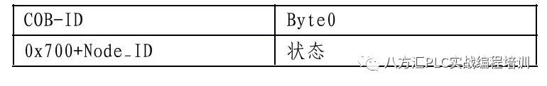
◆ The slave device can be configured to generate periodic messages called “heartbeat messages”, which periodically send the status of the slave device.
Monitoring of Master Devices
If the master device strictly requests protection information in a cyclic manner, the slave device can detect the status of the master device. If the slave device does not receive a request from the master device (protection error) within the defined lifetime, it will consider the master device to be faulty. In this case, the corresponding output enters an error state, and the slave device enters pre-processing state.
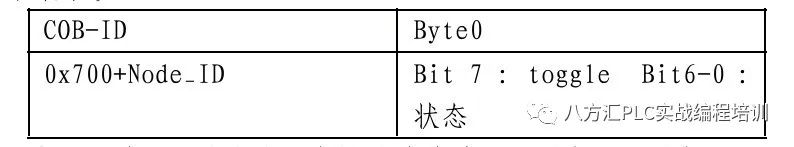
“Protection” Protocol
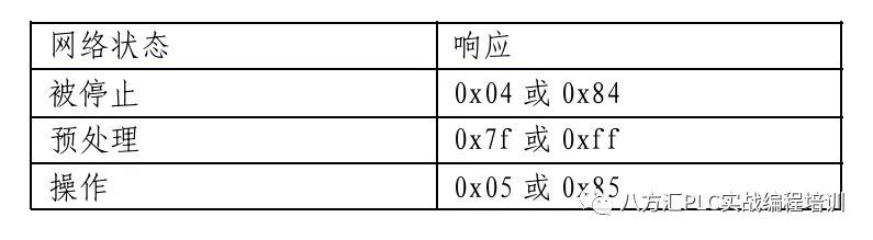
In the first “protection” message, the value of the “locked bit” (t) is 0, then in each subsequent protection message, this bit will change, indicating whether information has been lost. The bus header uses 7 remaining bits to indicate the network status:

There are the following types of devices in the CAN bus network:
(1) PLC: The PLC acts as a master station on CAN, serving as a central controller, coordinating, scheduling, and executing operations for the entire system. As a master station in the CAN network, the PLC can access any accessible data from any node in the network and perform bus monitoring, real-time monitoring of the working status of each node on the bus, and execute corresponding processing programs if errors occur;
(2) Distributed I/O: Typically consists of a power section, communication adapter section, and terminal block section. Distributed I/O does not have program storage and execution; the communication adapter section receives commands from the master station, drives I/O according to the master station’s instructions, and returns I/O inputs and fault diagnosis information to the master station.
(3) Field devices such as drives, sensors, actuators, etc.: These are field devices with CAN interfaces, which can be configured online by the master station for system configuration, parameter modification, data exchange, etc. The parameters that can be communicated and the parameter formats are determined by the CANopen standard.
Due to space limitations, this article has been shortened. The advertisements at the beginning and end of the article are for formal recruitment, power devices, SiC, GaN, digital power, and new energy manufacturers can cooperate. Interested parties can add WeChat ID 1768359031 for detailed discussions.Note:
Note: This article is sourced from the internet; the views expressed in the article are for sharing and exchange purposes only and do not represent the position of this public account. Please indicate the source if reprinted. If there are copyright issues, please notify us, and we will handle it promptly.
Power Electronics Technology and New Energy Contact List:

Important
How to download the high-definition PDF e-book of “Photovoltaic Inverter” in the section
Click the bottom of the articleRead the original text, visit the Power Electronics Technology and New Energy Forum (www.21micro-grid.com) to download!
Or forward the desired article to your friends circle without grouping or blocking, then screenshot and send it to the editor (WeChat:1413043922), the editor will send you the article after review!
Recommended Reading: Click the title to read
LLC_Calculator__Vector_Method_as_an_Application_of_the_Design
Some Notes Summarized on Power Supply Board Layout
High_Frequency_Transformers_for_HighPower_Converters_Materials
Huawei Electromagnetic Compatibility Structural Design Specification V2.0
Communication-less Coordinative Control of Paralleled Inverters
Soft Switching for SiC MOSFET Three-phase Power Conversion
Designing Compensators for Control of Switching Power Supplies
100KHZ 10KW Interleaved Boost Converter with full SiC MOSFET
Huawei – Single Board Thermal Design Training Material
Did you gain something from this? Please share it with more people
Announcement:
Due to space limitations, this article has been shortened. To obtain the original text, add the editor’s WeChat ID (QQ ID): 1413043922, please specify your research direction or industry (e.g., photovoltaic inverter hardware), the editor is optimistic about the market development of power electronics technology and new energy and is very interested in its key technologies. If you have technical questions, feel free to add the editor’s WeChat for discussion. Also, this public account has a WeChat group. If needed, you can also add the editor’s WeChat ID. Thank you!
More exciting content can be found below“Read the original text”!
Light up “Looking“, the editor’s salary goes up by 1 dime!