Good evening, my network engineer friends.
Today, let’s talk abouthow to establish campus network virtualization.
Unlike traditional campus networks that focus on individual devices, virtualized networks focus on the overall business experience of the entire network. Through iMaster NCE-Campus and VXLAN technology, network resources can be flexibly allocated.
By using virtualization technology, physical network resources are pooled, creating a comprehensive resource pool that can be flexibly allocated by iMaster NCE-Campus.
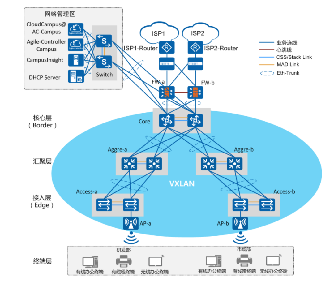
At the same time, multiple logically independent virtual networks can be created on a single physical network, each carrying different types of services and possessing relatively independent network resources, achieving decoupling of services and networks, which facilitates service management.
Virtualization technology retains the original hierarchical structure, data channels, and services provided in network design, ensuring that the end-user experience is the same as that of a dedicated physical network.
Multiple virtual networks sharing a single physical network can also improve resource utilization and reduce operational costs.
Let’s see how to do this next.
Today’s Article Reading Benefit:《Intelligent and Simplified Campus Network Solution: Typical Configuration Cases for Medium and Large Campus Networks (Virtualization Scenarios).pdf》
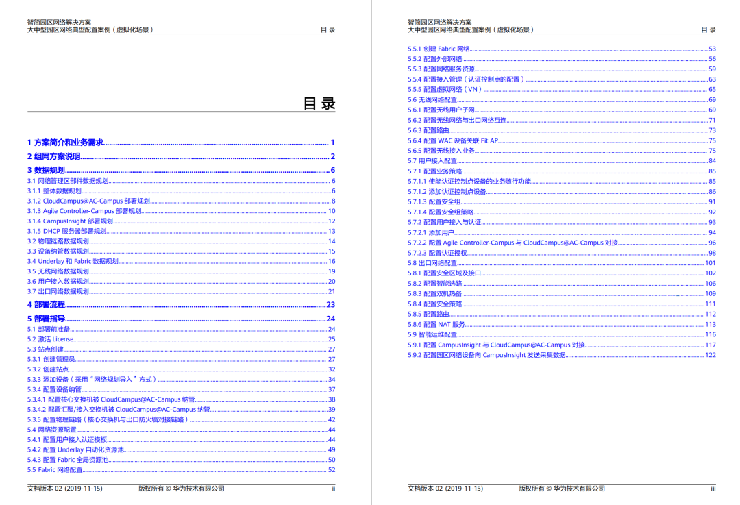
If your work scenario requires a virtualization solution for networking, then this document is very suitable for you. It is a 139-page PDF that thoroughly explains the process from data planning to deployment, guiding configuration for campus virtualization.
Add me as a friend and send the code“Virtualization,” to get limited resources.

The first 20 fans will receive free learning materials
01
Introduction to Campus Network Virtualization Solutions
Figure 1 shows the architecture of a campus virtual network, where Underlay refers to the physical network layer, and Overlay refers to the virtual network layer constructed on top of the Underlay using VXLAN technology.
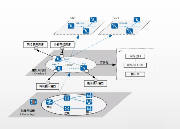
Figure 1 Campus Virtualization Network Architecture
Overlay consists of two parts: Fabric and VN.
Fabric: A pooled network that abstracts resources from the Underlay network. When creating instantiated virtual networks (VN), network resources from Fabric can be selected.
In the Fabric networking, further role division is made for the VXLAN Tunnel Endpoints (VTEP):
01 Border
The boundary gateway node of the Fabric network corresponds to physical network devices, providing data forwarding between the Fabric network and external networks. Generally, core switches that support VXLAN are used as Border.
02 Edge
The edge node of the Fabric network corresponds to physical network devices, where user traffic enters the Fabric network. Generally, access switches or aggregation switches that support VXLAN are used as Edge.
03 Virtual Network (VN)
The Virtual Network, by instantiating Fabric, can create logically isolated virtual network instances (VN1, VN2 in the figure).
Each VN corresponds to an isolated network (business network), such as a dedicated development network.
02
Introduction and Comparison of Distributed Gateway Solutions for Network Virtualization
Networking 1 Distributed VXLAN Gateway, with core switch as integrated WAC, VXLAN to access
Layer 2 or Layer 3 switch networking
VXLAN Roles: Core switch as Border, access switch as Edge
User Gateway: Wired user gateway at Edge, i.e., access switch; wireless user gateway at Border, i.e., core switch
Configuration Method:
-
Firewall: CLI/local Web management
-
Switch: CLI/iMaster NCE-Campus, prefer configuration delivery via iMaster NCE-Campus
-
WAC: CLI/local Web management, local Web management logs in via iMaster NCE-Campus
-
Wired Traffic: Enters VN from Edge, business-following policies are executed at Edge
-
Wireless Traffic: Tunnel forwarding, traffic enters VN from Border (i.e., integrated WAC), business-following policies are executed at Border
Networking 2 Distributed VXLAN Gateway, with aggregation switch as integrated WAC, VXLAN to aggregation
Layer 3 switch networking
VXLAN Roles: Core switch as Border, aggregation switch as Edge, access and aggregation deployment strategies are linked
User Gateway: Edge, i.e., aggregation switch
Configuration Method:
-
Firewall: CLI/local Web management
-
Switch: CLI/iMaster NCE-Campus, prefer configuration delivery via iMaster NCE-Campus
-
WAC: CLI/local Web management, local Web management logs in via iMaster NCE-Campus
-
Wired Traffic: Enters VN from Edge, business-following policies are executed at Edge.
-
Wireless Traffic: Tunnel forwarding, traffic enters VN from Edge (i.e., integrated WAC), business-following policies are executed at Edge
Networking 3 Distributed VXLAN Gateway, core switch integrated WAC, VXLAN to aggregation
Layer 3 switch networking
VXLAN Roles: Core switch as Border, aggregation switch as Edge
User Gateway: Wired user gateway at Edge, i.e., aggregation switch; wireless user gateway at Border, i.e., core switch
Configuration Method:
-
Firewall: CLI/local Web management
-
Switch: CLI/iMaster NCE-Campus, prefer configuration delivery via iMaster NCE-Campus
-
WAC: CLI/local Web management, local Web management logs in via iMaster NCE-Campus
-
Wired Traffic: Enters VN from Edge, business-following policies are executed at Edge.
-
Wireless Traffic: Tunnel forwarding, traffic enters VN from Border (i.e., integrated WAC), business-following policies are executed at Border
Networking 4 Distributed VXLAN Gateway, core switch with independent WAC, VXLAN to aggregation
Layer 3 switch networking
VXLAN Roles: Core switch as Border, aggregation switch as Edge, access and aggregation deployment strategies are linked
User Gateway: Wired user gateway at Edge, i.e., aggregation switch; wireless user gateway at Border, i.e., core switch
WAC Deployment VRRP Dual-Standby Explanation:
Since the ports connecting the independent WAC to the Border will be isolated by default configuration from iMaster NCE-Campus, when deploying VRRP dual-standby for independent WACs, a direct heartbeat line must be deployed between the independent WACs. @Network Engineer Club
03
Detailed Deployment Ideas for Distributed Campus Network Virtualization Solutions
This section introduces the deployment ideas commonly used in Layer 3 networking for distributed gateway solutions based on virtualization, where the aggregation switch acts as the Edge node and the core switch acts as the Border node.
User gateways are deployed in a distributed manner, selecting the aggregation switch as the user gateway, as shown in Figure 2.
The specific networking explanation is as follows:
To ensure device-level reliability, the firewall adopts a VRRP active-standby dual-machine hot backup, while core, aggregation, and access are stacked networks.
To ensure link-level reliability, Eth-Trunk networking is used between links.
The deployment of wireless services adopts a Fit AP+WAC architecture, with the core switch as the WAC device, and AP devices running in Fit AP mode.
The management layer components mainly involve iMaster NCE-Campus, iMaster NCE-Campus Insight, and DHCP servers.
As the number of servers or virtual machine resources for management layer components needs to be selected based on actual business needs, please refer to the specifications required in the product manual for each management layer component. In this case, the data planning for each component is selected to be of a smaller configuration specification. @Network Engineer Club
The servers installing management layer components are connected to the campus network through stacked Switches (Switch as the three-layer gateway for network management), and each server adopts dual network cards bound into a Bond interface (the binding mode of this group network adopts load balancing mode), then connected to the Switch’s Eth-Trunk interface, as shown in Figure 4-2.
If the management layer components are deployed in the data center machine room, the server-side networking can refer to the data center network solution.
The wiring requirements for the servers installing management layer components and data center switches can refer to the product manuals of each management layer component.
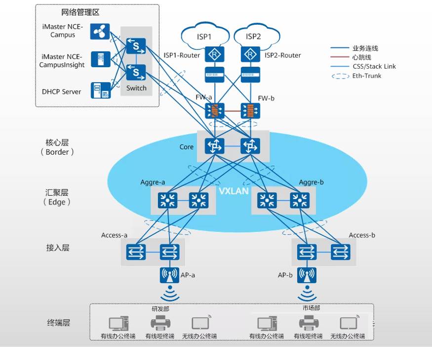
Figure 2 Distributed Gateway Scene Networking Diagram for Medium and Large Campus Virtualization Solutions (Aggregation as Edge and User Gateway, Core as Border)
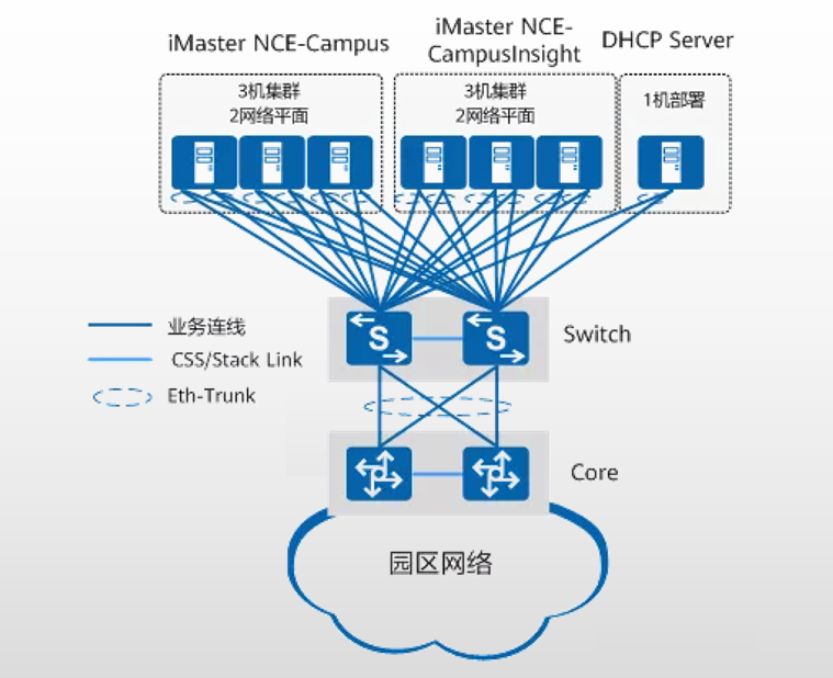
Figure 3 Physical Server Deployment Networking in the Network Management Area
04
Best Practices for Deploying Distributed Campus Network Virtualization Solutions
This section introduces detailed deployment practices for distributed gateway solutions for campus network virtualization based on common networking 3 in the introduction and comparison of the main networking for distributed gateway solutions.
The specific networking is a Layer 3 physical networking of VXLAN to aggregation, with the WAC using the Border device (i.e., core switch) as the integrated WAC. @Network Engineer Club
01 Specific Networking Situation
Layer 3 physical networking, with Fabric adopting VXLAN to aggregation.
The Border device (i.e., core switch) acts as the integrated WAC.
The Edge device serves as the wired user gateway; the Border device serves as the wireless user gateway.
02 Overall Data Planning
Each server installing components in the network management area adopts dual network cards bound, then connected to the stacked Switch, and the data planning for each component with the core switch is as shown in Figure 4;
The overall planning of IP addresses, VLANs, and other resources for each component during deployment is shown in Table 5-1, and more detailed deployment data planning will be introduced in the subsequent sections for each component.
Among them:
The gateway for components in the network management area is the Switch, which communicates with the Core through Layer 3 routing.
VLAN 4009 is used for iMaster NCE-Campus southbound, iMaster NCE-Campus Insight southbound, and management subnet communication.
VLAN 4012 is used for iMaster NCE-Campus southbound, DHCP server, and user subnet communication. @Network Engineer Club
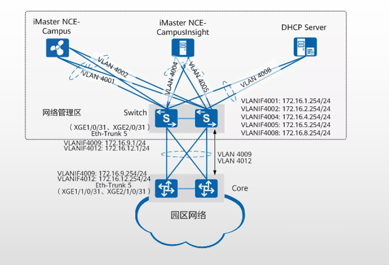
Figure 4 Data Planning for Communication between Network Management Area Components and Core Switch
03 Physical Link Data Planning
As shown in Figure 5, the physical link planning for medium and large campus virtualization solutions is not marked in the diagram for the communication link between the network management area and the core switch, which can be referred to in the overall data planning in the previous section “Data Planning for Network Management Area Components.”
In this case, the creation method of the aggregation link between different campus network devices is as follows:
Aggregation links between access, aggregation, and core switches: batch import aggregation link information to the site through the template in the “Import Network Planning.”
Aggregation links between the core switch and the network management area gateway: created manually on the device through the command line on both the core switch side and the network management area gateway side.
Aggregation links between the core switch and the firewall:
Created manually on the core switch side through iMaster NCE-Campus, and manually on the firewall side through its Web management.
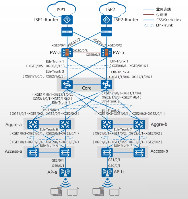
Figure 5 Physical Link Planning for Medium and Large Campus Virtualization Solutions
04 Device Management Data Planning
As shown in Figure 6, in this case, the core switch enables the NETCONF function through the command line, configuring the southbound address and port number of iMaster NCE-Campus to 172.16.2.5:10020, with the interface for southbound docking being VLANIF4009, and the IP address being 172.16.9.254/24.
After iMaster NCE-Campus manages the core switch, two management subnets are configured on the core switch, one for managing aggregation/access switches and one for managing APs.
Independent self-negotiated management VLANs are used for mutual communication between the core switch and aggregation/access switches, and between the core switch and APs.
The wired self-negotiated management VLAN is VLAN 4080, with the address pool interface being VLANIF4080 (IP address 192.168.100.254), and enabling the function of Option 148 carrying the southbound address of iMaster NCE-Campus (the address does not need to be manually configured, it is automatically negotiated); @Network Engineer Club
The wireless self-negotiated management VLAN is VLAN 4090, with the address pool interface being VLANIF4090 (192.168.200.254), and enabling Option 43 carrying the WAC address, with the WAC address being 192.168.200.254.
If the aggregation/access switches require fixed IP addresses for access in subsequent operation and maintenance management, the fixed IP address function can be enabled when configuring the management subnet.
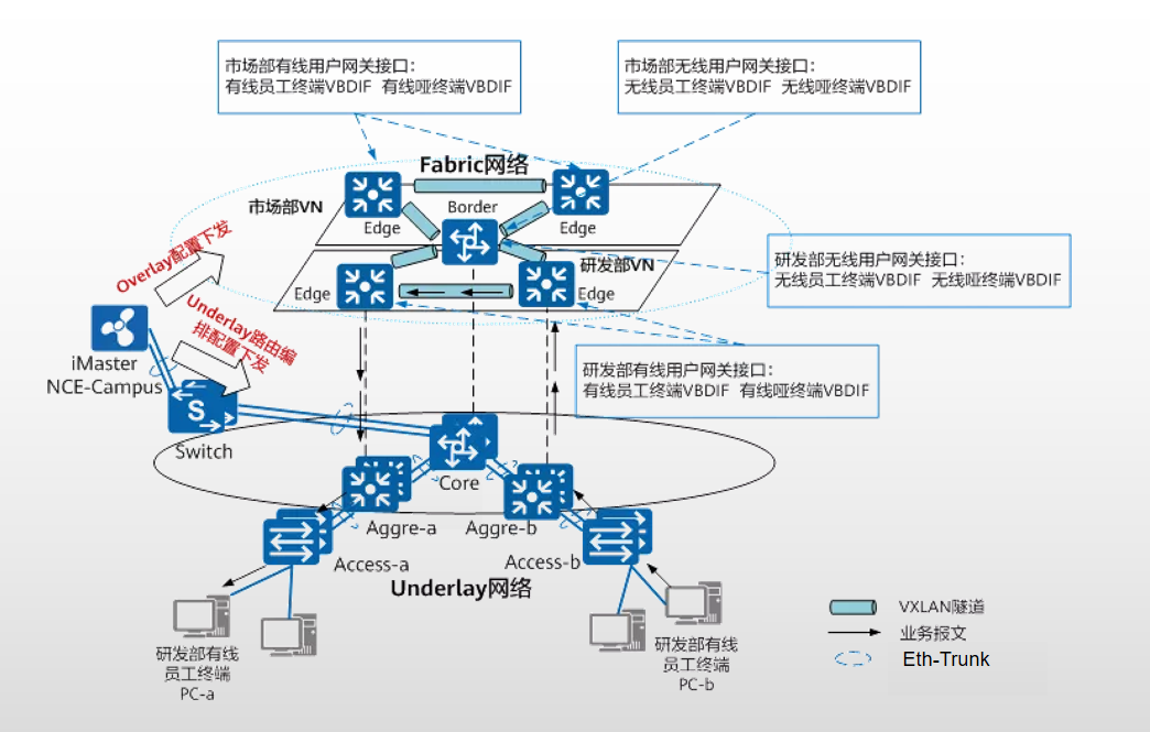
Figure 6 Data Planning for Management Network from Access Layer to Core Layer
05 User Subnet Data Planning
Underlay refers to the physical network layer that carries the upper-layer virtual network; it needs to ensure routability; Overlay is the virtual network layer constructed on top of the physical network layer using VXLAN technology.
Overlay includes Fabric and VN, where Fabric constructs a pooled network, and VN can select resources from Fabric as needed during construction;
Creating a VN (Virtual Network) is equivalent to instantiating Fabric, and a VN instance can represent a dedicated virtual network for a specific business. For example, in this case, RD_VN represents the R&D department network, and Market_VN represents the marketing department network.
The Border and Edge nodes of the Fabric network are VTEP nodes (VXLAN Tunnel Endpoints). @Network Engineer Club
In this case, the Fabric network using a distributed gateway has the core switch as the Border node, which is the gateway for wireless users;
while the aggregation switch as the Edge node serves as the wired user gateway.
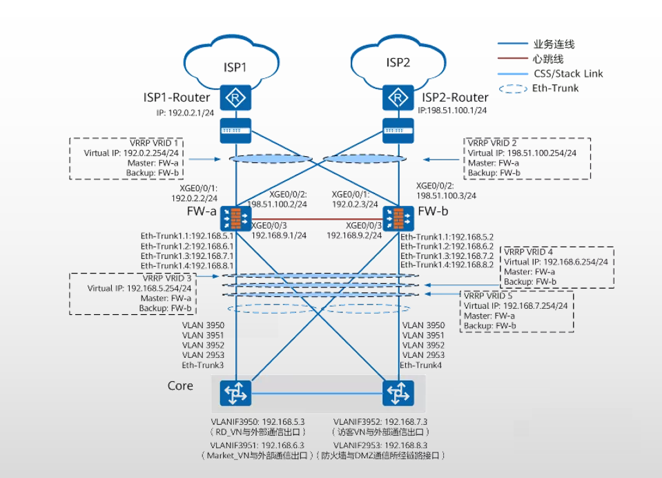
Figure 7 Layered Diagram of Underlay and Fabric
06 Exit Network Data Planning
The Border node in the Fabric network (i.e., Core device) adopts L3 exclusive exit to connect with the exit firewall device, meaning each VN has a corresponding Layer 3 interface connecting to the security zone of the firewall, enabling external access.
The guest network also has a corresponding Layer 3 interface connecting to the security zone of the firewall, enabling external access. The exit network data planning is shown in Figure 8.
Figure 8 Exit Network Data Planning for Medium and Large Campus Virtualization Solutions
Article Statement This article is compiled from online materials and published by the Network Engineer Club. Please indicate the source when reprinting; infringement will be deleted. Planning and Production Planning: Yiwei 丨 Supervisor: Shancheng城Editor: Yiwei 丨 Cover Image Source:Pexels and the internet, infringement will be deletedThose familiar with Lao Yang know that as long as I have time, I will answer questions for free, without charging any fans’ red envelopes.However, in order to filter out a group of fans who truly want to learn networking with Lao Yang, I provide you with a clean and efficient networking circle to truly return to technical communication; led by senior network engineer Lao Yang to initiate the network engineer circle[Network Engineer Club] Knowledge Planet for ICT industry technical practitioners.Share technology, experience, and resources with 1000+ network engineers.The planet containsmassive project case sharing, expert practical experience sharing, 1v1 Q&A, internal referral for network engineer positions,and manypractical tools and data,covering various technical knowledge points, industry data analysis reports, etc.If you are interested in networking or are currently learning about networking, welcome to join my high-quality networking exchange circle. How to join the Knowledge Planet? Knowledge Planet Pricing: Original Price299 yuan/yearLimited Time Discount Price99 yuan/year Identify the QR code below to add Lao Yang as a friend Friend verification, please note“Knowledge Planet” Remember to find Lao Yang before joining to receive a 200 yuan discount coupon for the planet (limited quantity)