↑ Click on the blue text above “ PLC Enthusiasts ” to follow us!
Introduction: In the workplace, communication with other devices is often required, and the ABB robot, as one of the four major families, has extremely rich communication functions. If communication with a PLC is needed on-site, and the PLC supports the MODBUS TCP communication protocol, ABB does not provide standard MODBUS-related processing functions. To use MODBUS/TCP, you can use ordinary sockets for sending and receiving, according to the MODBUS TCP format for data transmission. ABB industrial robots do not have dedicated instructions, so they can only act as clients. The client connection program can be placed in the initialization program and connected each time it runs.
To use the MODBUS TCP communication protocol, it is essential to understand its information frame format:
MODBUS TCP combines the MODBUS protocol and TCP/IP network standards. It is the specific implementation of the MODBUS protocol over TCP/IP. During data transmission, MODBUS application data units are inserted into TCP packets. The Modbus protocol assigns the TCP port number 502, which is currently the only allocated port number in the instrumentation and automation industry, and the hardware interface used is the Ethernet interface.
The MODBUS TCP information frame consists of three parts: message header, function code, and data. The message header is made up of four parts, totaling 7 bytes. Compared to MODBUS RTU, MODBUS TCP does not have CRC checks; the check is completed by the TCP/IP protocol and the Ethernet link layer.

Information Frame Interpretation:
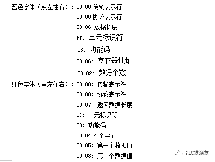
Transmission Identifier: 2 bytes in length, indicating the transmission of Modbus inquiry/response, generally defaulting to 00 00.
Protocol Identifier: 2 bytes in length, 00 00 indicates the Modbus protocol.
Data Length: 2 bytes in length, indicating the number of data items from the unit identifier onwards.
Unit Identifier: 1 byte in length, equivalent to the slave address in MODBUS RTU communication.
Function Code: 1 byte in length. It can be used to read device data or write data to the device.
Data: Composed of n bytes, depending on the length of the data being read.
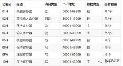
Function Code (determines whether to write or read data):
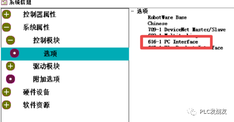
1. MODBUS/TCP is based on Ethernet, so when using ABB robots, the 616-1PCINTERFACE option is required. (In the robot main menu, select “System Information” to view the options.)
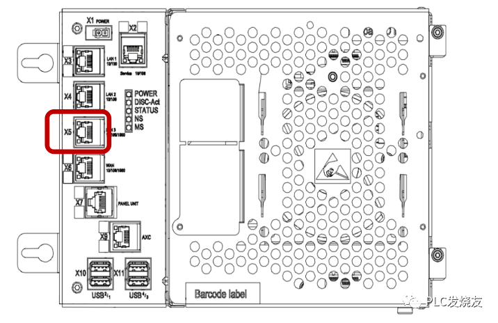
2. The MODBUS/TCP communication medium can use ordinary network cables, but the cable must connect to the “X5” port of the robot controller.
Case Study:
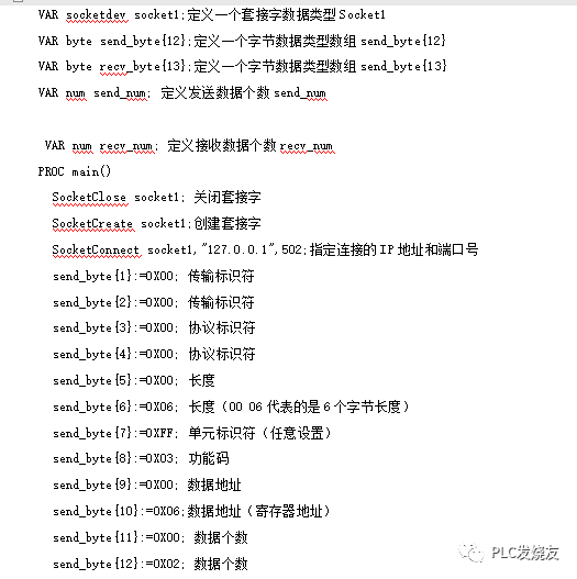
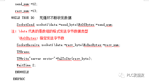
1. The ABB robot now needs to read the value of the holding register in the debugging tool, starting from the 6th byte to read 2 words, using function code 0X03. (The debugging tool is set to IP address 127.0.0.1, port number 502.)
2. The data read is displayed on the robot’s teach pendant.
3. The robot acts as a client, while the debugging tool acts as a server.
Robot-side Program Development:
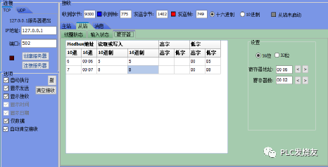
In the MODBUDS debugging tool, set the IP address and port number (127.0.0.1 and 502), and manually assign values of 5 and 8 to addresses 00 06 and 00 07 respectively.
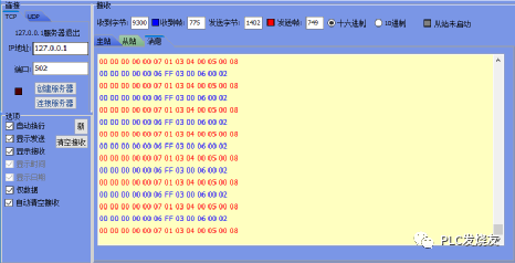
In the “Messages” section of the MODBUDS debugging tool, you can see the information frame data (blue text represents the data sent from the robot to the debugging tool, while red text represents the data sent from the debugging tool to the robot).
Source: PLC Enthusiasts, Author: Ji Cheng – Guo Biao, Please indicate the source when reprinting! Free offer of “MODBUDS Debugging Tool” in the article, Follow the public account “PLC Enthusiasts”, reply: Debugging Tool, and you can receive it for free! Comments can supplement parts of the article that are incorrect or lacking, so that the next reader can learn more; what you know is what everyone needs…
Previous Recommendations
Step-by-step guide on how to achieve multi-speed control of inverters
What posture should electricians use to send New Year blessings to show sincerity?
Using counters in S7-300 PLC to achieve single-button start-stop
Introduction to Mitsubishi FX5U PLC’s FUN general functions (Part 2)
Siemens SCL advanced language [FOR loop statement]
A comprehensive guide to understanding capacitors, worth saving!
Introduction to Mitsubishi FX5U PLC’s FUN general functions (Part 1)
Controlling servos with 1500PLC, programming is actually this simple!