
01
Start, Self-locking, and Stop Control
PLC Circuit and Ladder Diagram
Start, self-locking, and stop control are the most basic control functions of PLC. These can be implemented using output instructions (OUT) or set/reset instructions (SET, RST).
1. Using Coil Drive Instructions for Start, Self-locking, and Stop Control
The coil drive (OUT) instruction functions to connect the output coil to the right bus. It is a commonly used instruction.
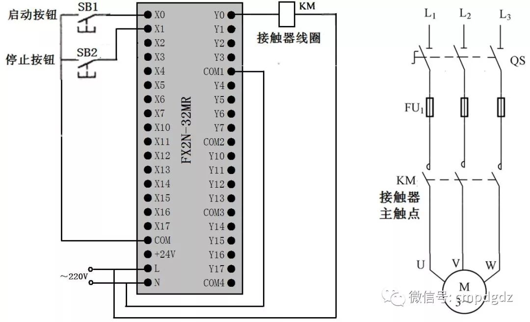
PLC Wiring Diagram
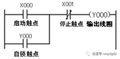
Ladder Diagram
When the start button SB1 is pressed, the start contact X000 in the internal ladder diagram of the PLC closes, and the output coil Y000 gets power. The internal hard contact of the output terminal Y0 closes, connecting the terminal Y0 with the terminal COM, energizing the contactor coil KM, causing the main contact of KM in the main circuit to close, and the motor starts.
After the output coil Y000 gets power, in addition to closing the hard contact between Y000 and COM, it will also close the self-locking contact Y000. When the start contact X000 is disconnected, the self-locking contact closure maintains power to the coil Y000, allowing the motor to continue running, thus achieving self-locking control.
When the stop button SB2 is pressed, the stop contact X001 in the internal ladder diagram of the PLC opens, and the output coil Y000 loses power. The internal hard contact between terminals Y0 and COM opens, de-energizing the contactor coil KM, and the main contact of KM in the main circuit opens, causing the motor to stop.
2. Using Set/Reset Instructions for Start, Self-locking, and Stop Control
The ladder diagram for using Set and Reset instructions (SET, RST) to implement start, self-locking, and stop control is shown in the figure below, and the PLC wiring diagram is the same as the one above.
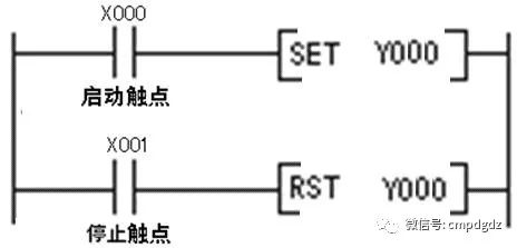
Ladder Diagram
When the start button SB1 is pressed, the start contact X000 in the ladder diagram closes, and the instruction [SET Y000] is executed. The result of this instruction sets the output relay coil Y000 to 1, which is equivalent to powering the coil Y000, causing the internal hard contact between terminals Y0 and COM to close, energizing the contactor coil KM, and the main contact of KM in the main circuit closes, allowing the motor to start.
After the coil Y000 is set, releasing the start button SB1 will disconnect the start contact X000, but the coil Y000 will remain in the “1” state, i.e., it will still be powered, allowing the motor to continue running, thus achieving self-locking control.
When the stop button SB2 is pressed, the stop contact X001 in the ladder program closes, and the instruction [RST Y000] is executed. The result of this instruction resets the output coil Y000, which is equivalent to de-energizing the coil Y000. The internal hard contact between terminals Y0 and COM opens, de-energizing the contactor coil KM, and the main contact of KM in the main circuit opens, causing the motor to stop.
Both using Set/Reset instructions and coil drives can achieve start, self-locking, and stop control; the PLC wiring for both is the same, only the ladder diagram program written for the PLC input differs.
02
Forward and Reverse Interlocking Control
PLC Circuit and Ladder Diagram
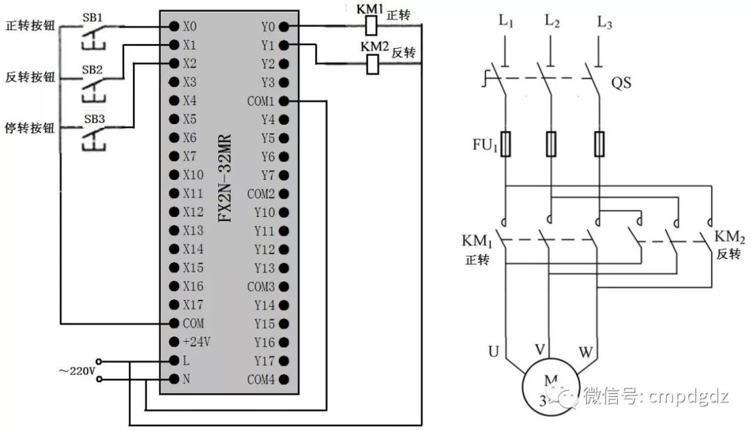
PLC Wiring Diagram
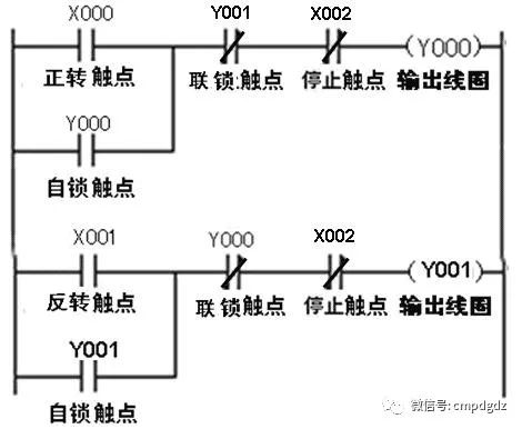
Ladder Diagram
Forward interlocking control: Press the forward button SB1 → Ladder diagram program’s forward contact X000 closes → Coil Y000 gets power → Y000 self-locking contact closes, Y000 interlocking contact opens, Y0 terminal and COM terminal’s internal hard contact closes → Y000 self-locking contact closes, allowing coil Y000 to remain powered even after the X000 contact opens; Y000 interlocking contact opens, preventing coil Y001 from getting power even if X001 contact closes (due to misoperation SB2), achieving interlocking control; Y0 terminal and COM terminal’s internal hard contact closes, energizing contactor KM1, main contact of KM1 closes in the main circuit, allowing the motor to run forward.
Reverse interlocking control: Press the reverse button SB2 → Ladder diagram program’s reverse contact X001 closes → Coil Y001 gets power → Y001 self-locking contact closes, Y001 interlocking contact opens, Y1 terminal and COM terminal’s internal hard contact closes → Y001 self-locking contact closes, allowing coil Y001 to remain powered even after the X001 contact opens; Y001 interlocking contact opens, preventing coil Y000 from getting power even if X000 contact closes (due to misoperation SB1), achieving interlocking control; Y1 terminal and COM terminal’s internal hard contact closes, energizing contactor KM2, main contact of KM2 closes in the main circuit, allowing the motor to run in reverse.
Stop control: Press the stop button SB3 → Both stop contacts X002 open → Coils Y000 and Y001 lose power → Contactors KM1 and KM2 coils lose power → Main contacts of KM1 and KM2 open in the main circuit, causing the motor to stop.
03
Multi-location Control
PLC Circuit and Ladder Diagram
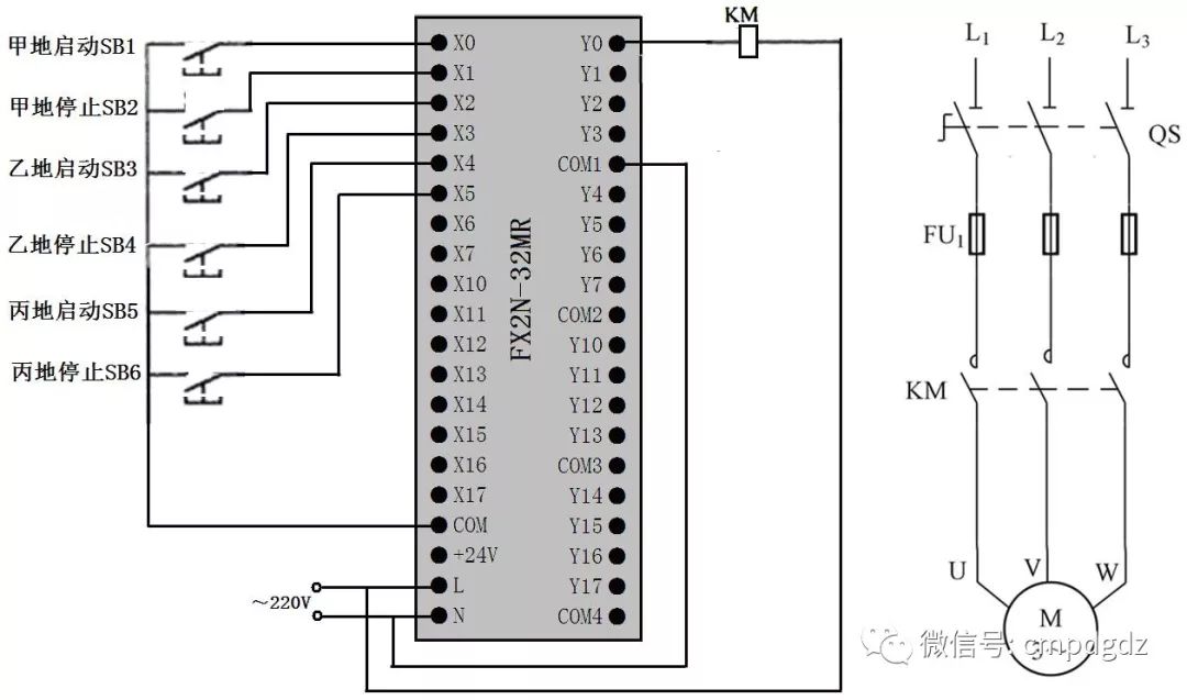
PLC Wiring Diagram
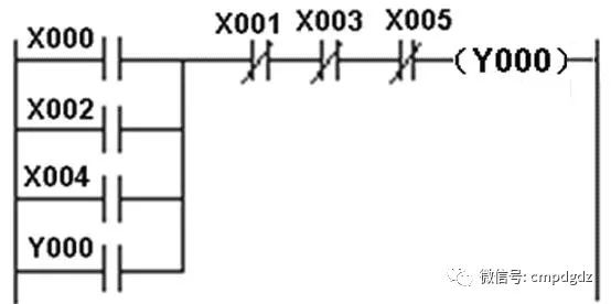
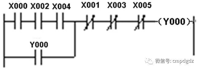
Single Person Multi-location Control Ladder Diagram
1. Single Person Multi-location Control
Control at Location A. When the start button SB1 is pressed → X000 normally open contact closes → Coil Y000 gets power → Y000 normally open self-locking contact closes, Y0 terminal’s internal hard contact closes → Y000 normally open self-locking contact locks Y000 coil power supply, Y0 terminal’s internal hard contact closes to energize contactor coil KM → Main contact of KM closes in the main circuit, allowing the motor to run.
Stop Control at Location A. When the stop button SB2 is pressed → X001 normally closed contact opens → Coil Y000 loses power → Y000 normally open self-locking contact opens, Y0 terminal’s internal hard contact opens → Contacting coil KM loses power → Main contact of KM opens in the main circuit, causing the motor to stop.
The start/stop control at locations B and C is the same as at location A. The ladder diagram allows for start/stop control at any location, and it is also possible to start at one location and stop at another.
2. Multi-person Multi-location Control
Start Control. When the buttons at locations A, B, and C are pressed simultaneously SB1, SB3, SB5 → Coil Y000 gets power → Y000 normally open self-locking contact closes, Y0 terminal’s internal hard contact closes → Y000 coil power locks, energizing contactor coil KM → Main contact of KM closes in the main circuit, allowing the motor to run.
Stop Control. When any of the stop buttons at locations A, B, and C are pressed SB2, SB4, SB6 → Coil Y000 loses power → Y000 normally open self-locking contact opens, Y0 terminal’s internal hard contact opens → Y000 normally open self-locking contact opens, cutting off the power supply to coil Y000, Y0 terminal’s internal hard contact opening causes contactor coil KM to lose power → Main contact of KM opens in the main circuit, causing the motor to stop.
The ladder diagram above can achieve the functionality that multiple persons must simultaneously press the start button to start, while stop control can be performed at any location.
04
Timing Control
PLC Circuit and Ladder Diagram
There are many timing control methods; below are two typical timing control PLC circuits and ladder diagrams.
1. Delayed Start Timing Control PLC Circuit and Ladder Diagram
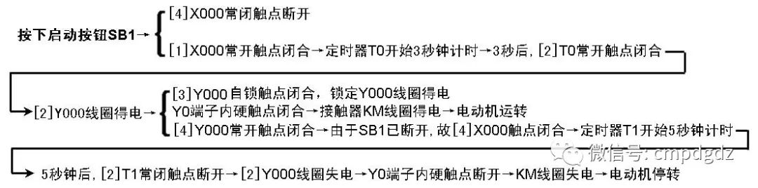
The PLC circuit and ladder diagram for delayed start timing control is shown in the figure below, which can achieve the following functionality: After pressing the start button, the motor starts running after 3 seconds, and automatically stops after 5 seconds.
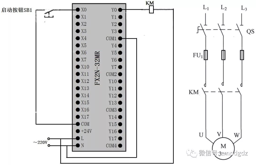
PLC Wiring Diagram
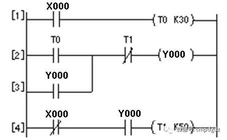
Ladder Diagram
2. Multi-timer Combination Control PLC Circuit and Ladder Diagram
The following figure shows a typical multi-timer combination control PLC circuit and ladder diagram, which can achieve the following functionality: After pressing the start button, motor B runs immediately, 30 seconds later, motor A starts running, after 70 seconds, motor B stops, and after 100 seconds, motor A stops.
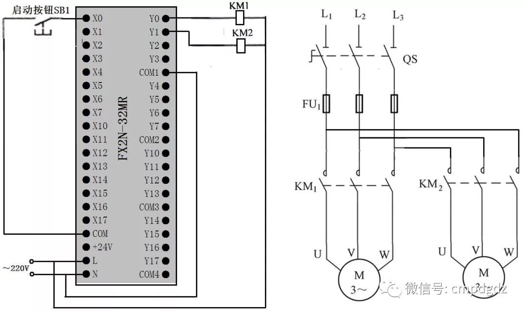
PLC Wiring Diagram
Ladder Diagram
05
Timer and Counter Combination Extended Timing Control
PLC Circuit and Ladder Diagram
The maximum timing time for Mitsubishi FX series PLCs is 3276.7 seconds (approximately 54 minutes). By using timers and counters, the timing duration can be extended.
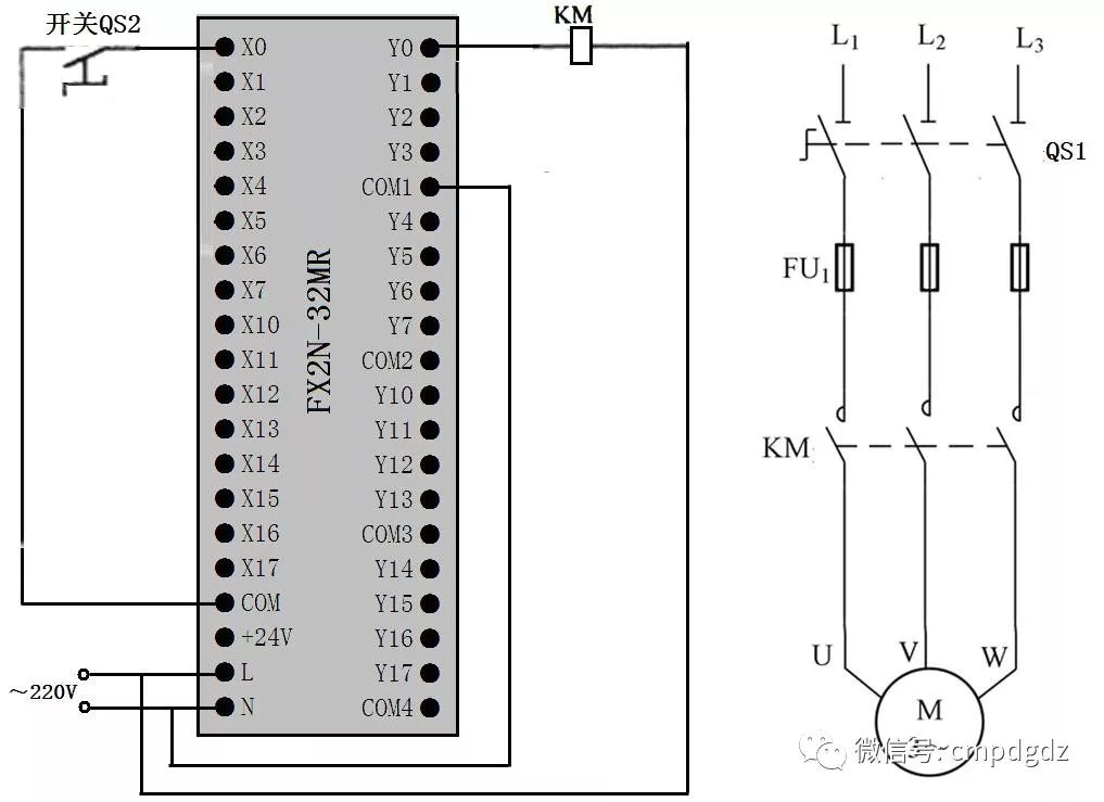
PLC Wiring Diagram

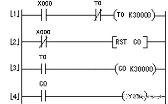
Ladder Diagram

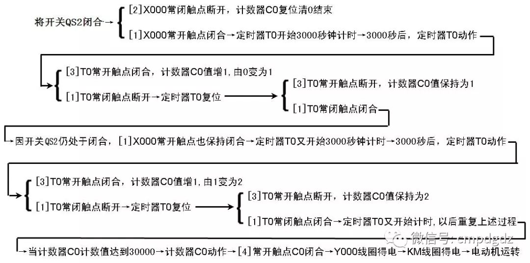
In the figure, the timer T0 has a timing unit of 0.1s ( 100ms), and when combined with counter C0, the timing duration T = 30000 × 0.1 seconds × 30000 = 90000000 seconds = 25000 hours. If a reset is required, disconnect switch QS2, let [2]X000 normally closed contact close, execute the [RST C0] instruction to reset counter C0, then reconnect QS2, and it will restart the 250000 hour timing.
06
Multiple Output Control
PLC Circuit and Ladder Diagram
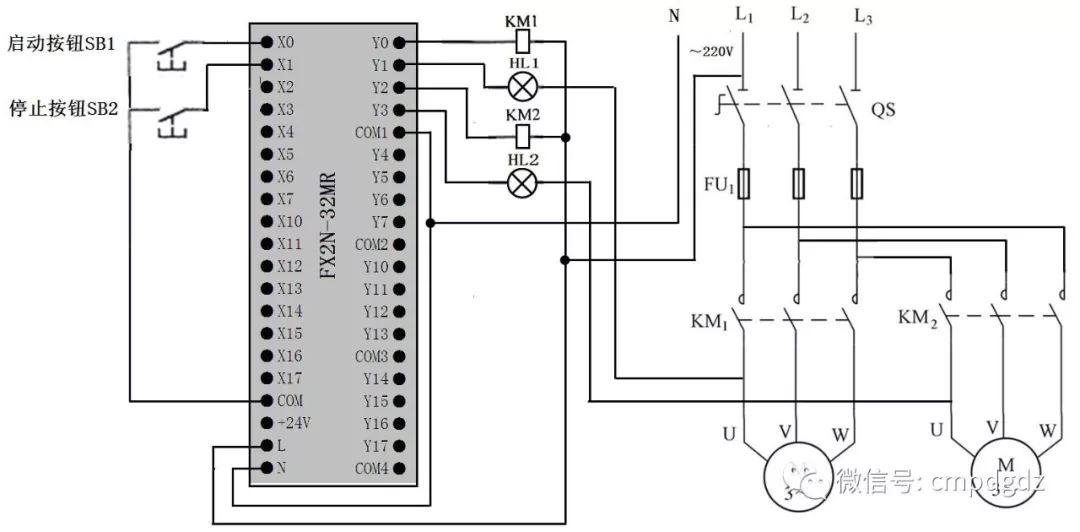
PLC Wiring Diagram
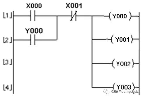
Ladder Diagram
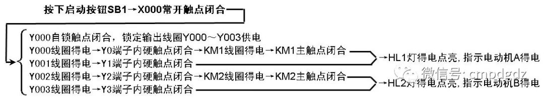
1. Start Control
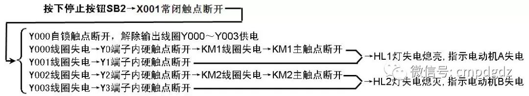
2. Stop Control
07
Overload Alarm Control
PLC Circuit and Ladder Diagram
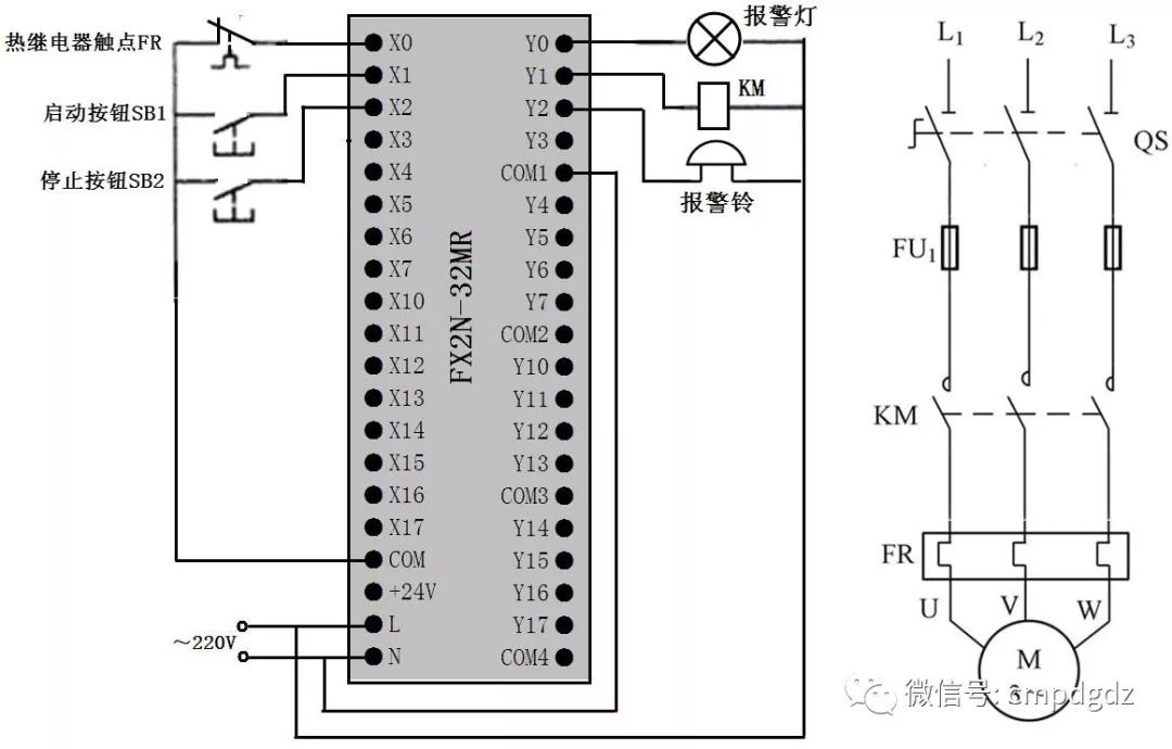
PLC Wiring Diagram
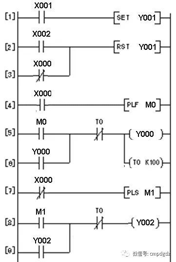
Ladder Diagram
1. Start Control
Press the start button SB1 → [1]X001 normally open contact closes → [SET Y001] instruction is executed → Y001 coil is set, meaning Y001 coil gets power → Y1 terminal’s internalhard contact closes → Contactor KM coil gets power → KM main contact closes → Motor gets power and runs.
2. Stop Control
Press the stop button SB2 → [2]X002 normally open contact closes → [RST Y001] instruction is executed → Y001 coil is reset, meaning Y001 coil loses power → Y1 terminal’s internalhard contact opens → Contactor KM coil loses power → KM main contact opens → Motor loses power and stops.
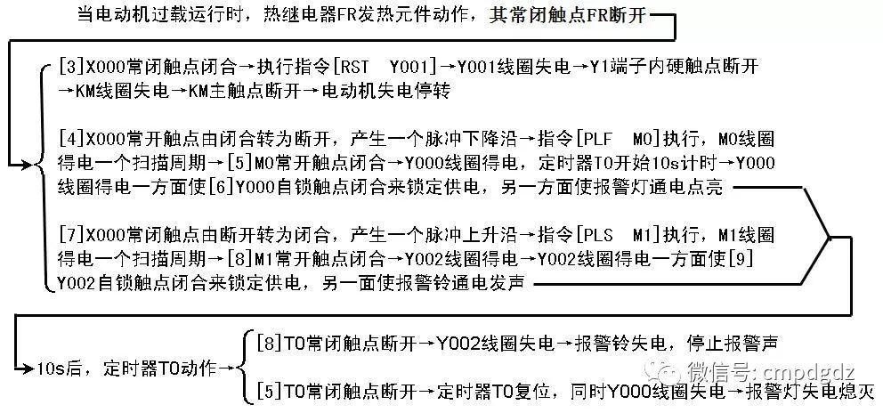
3. Overload Protection and Alarm Control

08
Flashing Control
PLC Circuit and Ladder Diagram
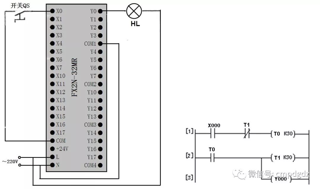
PLC Wiring Diagram and Ladder Diagram
Close switch QS → X000 normally open contact closes → Timer T0 starts 3 seconds timing → 3 seconds later, timer T0 acts, T0 normally open contact closes → Timer T1 starts 3 seconds timing, at the same time Y000 gets power, Y0 terminal’s internal hard contact closes, lamp HL lights up → 3 seconds later, timer T1 acts, T1 normally closed contact opens → Timer T0 resets, T0 normally open contact opens → Y000 coil loses power, simultaneously timer T1 resets → Y000 coil loses power, turning off lamp HL; timer T1 resets, causing T1 to close, since switch QS remains closed, X000 normally open contact also remains closed, timer T0 starts again 3 seconds timing.
Repeat the above process, the lamp HL keeps flashing with a frequency of 3 seconds on, 3 seconds off.
END
This article is excerpted from “PLC and Inverter Technology Learning”, an original article. Please contact the editor for reprints.
Click the image to quickly purchase the book
We welcome everyone to improve the above content, discuss and grow knowledge together. Meanwhile, feel free to join our WeChat group. Please add the editor’s WeChat, and we will invite you to join.