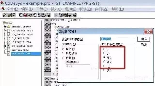
Currently, there are 5 standard programming languages for PLCs, including graphical programming languages and textual programming languages.
Graphical programming languages include:
Ladder Diagram (LD);
Function Block Diagram (FBD);
Sequential Function Chart (SFC).
Textual programming languages include:
Instruction List (IL) & Structured Text (ST).
The programming languages of IEC 1131-3 were formed based on the reasonable absorption and reference of programming languages from PLC manufacturers worldwide by the IEC working group, establishing an international programming language standard for industrial control systems. It is applicable not only to PLC systems but also to a broader industrial control field, making significant contributions to the global standardization of PLC programming languages.
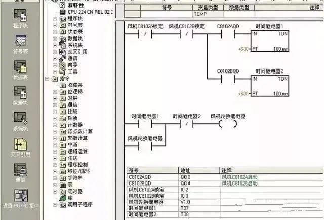
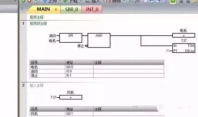
Ladder Diagram (LD)
Ladder Diagram (LD) is the first programming language adopted by PLCs and is also the most commonly used programming language for PLCs.
The ladder diagram programming language evolved from the schematic diagrams of relay control systems, maintaining the basic concepts of relay control systems while differing in symbols and expression methods.
The design intention of PLCs is to be used by electrical technicians in factory workshops, to align with the thinking habits of relay control circuits.
As the first programming language used in PLCs, ladder diagrams retain the style and habits of relay circuit diagrams, making it the most easily accepted and used language by electrical technicians.
1. Soft Relay
Some programming elements in PLC ladder diagrams retain the name of relays, such as input relays, output relays, internal auxiliary relays, etc. However, they are not real physical relays, but rather storage units (soft relays), each corresponding to a storage unit in the PLC memory image register.
If the storage unit is in the “1” state, it indicates that the corresponding soft relay coil in the ladder diagram is “energized”, its normally open contacts are closed, and normally closed contacts are open, referred to as the “1” or “ON” state of the soft relay.
If the storage unit is in the “0” state, the corresponding soft relay coil and contact states are the opposite of the above, referred to as the “0” or “OFF” state of the soft relay. These “soft relays” are also often called programming elements.
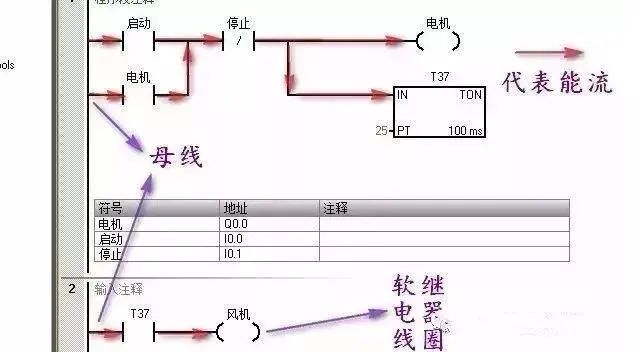
2. Power Flow
There is an imaginary “conceptual current” or “power flow” flowing from left to right, which aligns with the logical operations during user program execution.
Power flow can only flow from left to right. Utilizing this concept helps us better understand and analyze ladder diagrams.
3. Bus Bar
The vertical common lines on both sides of the ladder diagram are called bus bars.
When analyzing the logical relationships in ladder diagrams, to borrow the analytical methods of relay circuit diagrams, one can imagine a left positive and right negative DC power supply voltage between the left bus bar and the right bus bar, with “power flow” moving from left to right. The right bus bar may not be drawn.
4. Logical Calculation of Ladder Diagrams
Based on the states of the contacts in the ladder diagram and their logical relationships, the states of the programming elements corresponding to each coil in the diagram are determined, known as the logical calculation of the ladder diagram.
Logical calculations in ladder diagrams proceed from left to right and top to bottom. The results of the calculations can immediately be utilized by subsequent logical calculations.
Logical calculations are based on the values in the input image registers, rather than the instantaneous states of external input contacts.
1. Corresponds to the electrical operation schematic, providing intuitiveness and correspondence;
2. Consistent with existing relay logic control technology, making it easy for electrical technicians to master and learn;
3. The difference from existing relay logic control technology is that the power flow in the ladder diagram is not actual current, and the internal relays are not physically existing relays. Therefore, when applying it, one must distinguish it from the concepts related to existing relay logic control technology;
4. There is a one-to-one correspondence with instruction list programming languages, facilitating mutual conversion and program checking.
Function Block Diagram (FBD)
Function Block Diagram (FBD) uses graphical symbols similar to digital logic gate circuits, making logic intuitive and easy to use. It has instructions equivalent to contacts and coils in ladder diagram programming, capable of solving a wide range of logical problems.
1. Uses functional modules as units, starting from control functions, making analysis and understanding of control schemes easier;
2. Functional modules describe functions graphically, greatly facilitating programming and configuration for designers, with good operability;
3. For systems with larger control scales and complex control relationships, the relationships between control functions can be clearly expressed, thus reducing programming and configuration time and debugging time.
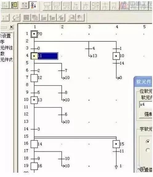
Sequential Function Chart (SFC)
Sequential Function Chart (SFC), also known as flow charts or state transition diagrams, is a graphical functional description language specifically used to describe industrial sequential control programs. It can be used to program systems with complex structures such as concurrency and selection.
1. Focuses on functionality, clearly organized, facilitating understanding and communication of program operations;
2. For large programs, it allows for collaborative design and employs a more flexible program structure, saving programming and debugging time;
3. Commonly used in cases of large-scale systems with complex program relationships;
4. Only when the commands and operations of the active steps are executed, the transitions after the active steps are scanned, thus significantly reducing the overall program scanning time compared to other program structures.
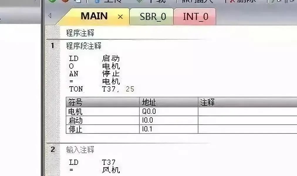
Instruction List (IL)
Instruction List (IL) programming language is similar to mnemonic assembly language in computers. It is the most basic programming language for programmable controllers. Instruction list programming uses one or several easily memorable characters to represent a certain operational function of the programmable controller.
1. Uses mnemonics to represent operational functions, making it easy to remember and grasp;
2. Uses mnemonics on the programming device’s keyboard, making it user-friendly and allowing programming design without a computer;
3. Has a one-to-one correspondence with ladder diagrams, with characteristics similar to ladder diagram languages.
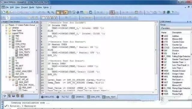
Structured Text (ST)
Structured Text (ST) is a high-level text language that can describe functions, function blocks, and the behavior of programs. It can also describe steps, actions, and transitions in sequential function charts.
Structured text language superficially resembles PASCAL but is a programming language specifically developed for industrial control applications, with strong programming capabilities for variable assignment, callback functions, function blocks, creating expressions, writing conditional statements, and iterative programming.
1. Uses high-level languages for programming, capable of handling more complex control operations;
2. Requires knowledge of high-level computer programming languages and programming skills, posing a higher skill requirement for programmers, making it difficult for ordinary electrical personnel to complete;
3. Performance in intuitiveness and operability is relatively poor;
4. Often used for implementing control functions that are difficult to achieve with other languages such as functional modules.
Note: Not all PLCs support all programming languages (e.g., many lower-end PLCs do not support function block diagrams and sequential function charts), but large PLC control systems generally support these 5 standard programming languages or similar programming languages.
There are also some programming languages that are not part of the standard. Although they were not selected for the standard languages, they were developed for specific applications and may be better programming languages in certain situations.
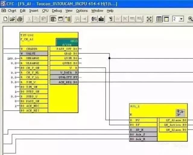
For example, the Continuous Function Chart (CFC) of D7-SYS is specifically developed for large continuous process control. By simply calling the CFC function blocks in the program, one can easily achieve a series of special functions such as PID controllers, counters, positioners, ramp function generators, etc., without needing specialized programming knowledge, just requiring an understanding of graphical processing and the use of standard program blocks for simple settings.
Discussing PLC Learning Methods
1. Learning PLC programming requires strong willpower and enough patience
Everyone has their strengths. Some see programming as a tedious and lengthy task; others view it as an interesting intellectual game. If you are the former, it is strongly advised to stay away from this job.
After all, programming work challenges a person’s willpower and patience, requiring numerous trials and errors, debugging-modifying-debugging-modifying… After countless failures, when you see the PLC running in an orderly manner according to your control requirements, you will gain immense satisfaction, similar to clearing a level in a game.
2. Learning PLC programming requires confidence in practical application
Many beginners often hesitate to operate practically out of fear of damaging equipment. In fact, these fears are unfounded; as long as you carefully read the manuals and follow standard protocols for wiring and practical operations, nothing should go wrong.
Do not worry about potential issues with the programs you write affecting the normal operation of the PLC; problems can only be discovered once the PLC is running. Therefore, having the confidence to practice boldly is essential for PLC programming.
3. Programming requires meticulous logical thinking
Programming itself is a logical thinking process.
The original PLCs were designed to replace relay logic circuits, thus inheriting the description method based on relay contacts as triggering conditions.
In PLCs, virtual contacts replace relay contacts, while the logical relationships expressed by relay circuits are preserved. Therefore, sorting out the logical relationships between objects requires meticulous logical thinking.
4. Develop good programming habits
Everyone has different habits and characteristics in programming, and uniformity cannot be forced. However, some good habits should be followed by the majority.
1. Sort out logical and temporal relationships, and prepare program flow charts;
2. Reasonably allocate main programs, subprograms, and interrupt programs;
3. Reasonably allocate registers and prepare register symbol tables.
Many PLC operations are directly aimed at registers. If there are unreasonable overlaps in register addresses in the program, it may cause program errors.
Preparing a register symbol table can not only avoid the above problems but also enhance the readability of the program.
PLCs provide rich instructions and modules. Beginners should first use simple instructions to achieve their goals, which will help them understand more complex instructions. After gaining some experience, they should consider mastering the application of complex instructions and optimizing programs.
5. Have a certain foundation in program design knowledge
Having a certain foundation in program design knowledge and understanding the relevant theories of PLC program design is important.
Without theoretical preparation or guidance in this area, relying solely on practical exploration may work for simple problems, but complex ones will be much more challenging, leading to wasted time and energy without producing high-quality programs.
Ultimately, any theory is just a summary of experience, and it all comes from practice.
-
(Content sourced from the internet, copyright belongs to the original author)
-
Disclaimer: If there are copyright issues, please contact for deletion! No individual or organization assumes relevant legal responsibilities.
-