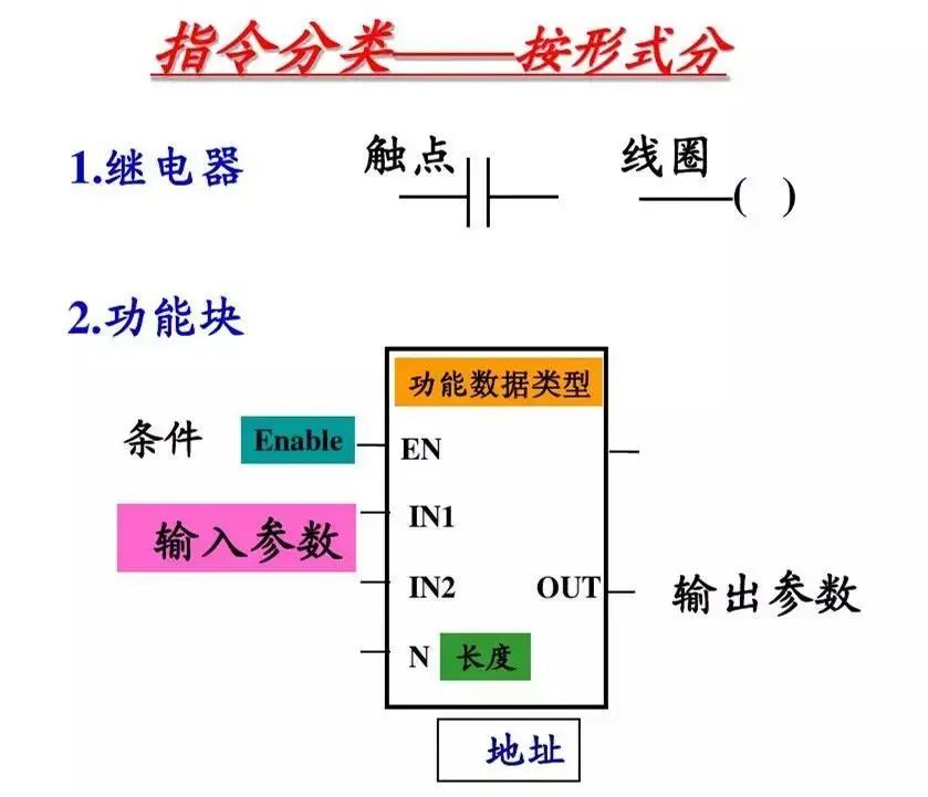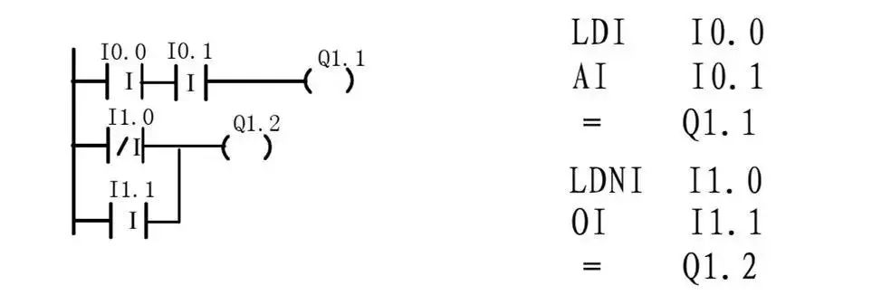
1. Contact and Coil Instructions
Programming Principles of PLC Ladder Diagram Language
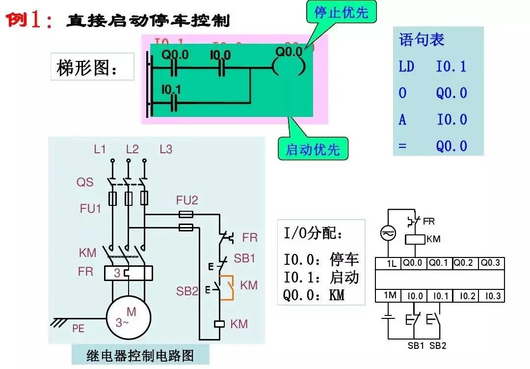
1. The ladder diagram consists of multiple rungs, each coil can form a rung, and each rung has multiple branches, representing a logical equation;
2. The relays, contacts, and coils in the ladder diagram are not physical but are bits in the PLC memory (1=ON; 0=OFF); normally open/closed contacts can be referenced infinitely during programming, while coil outputs can only be referenced once;
3. The flow in the ladder diagram is not physical current but “conceptual current” that only flows from left to right;
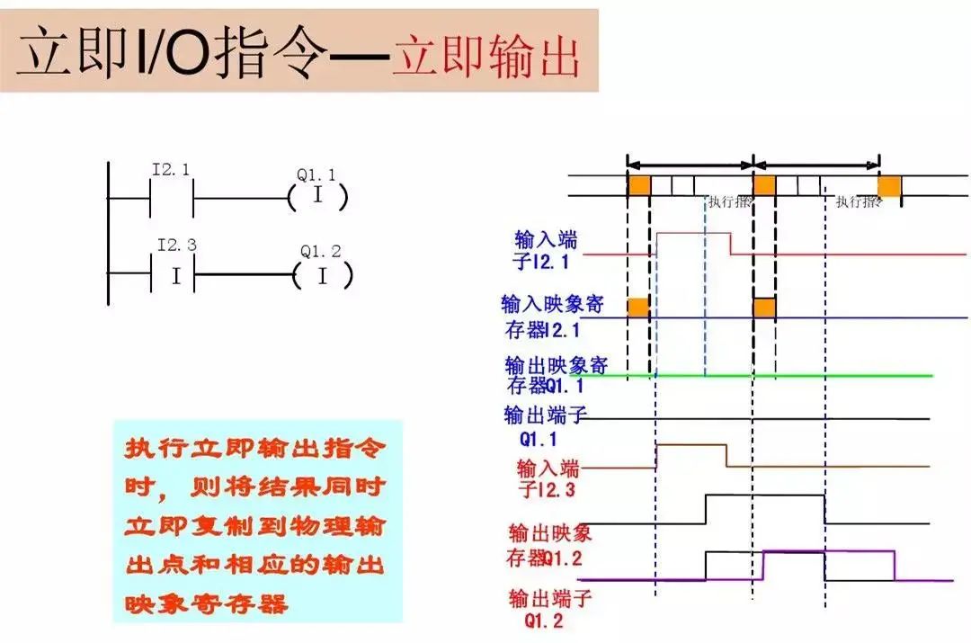
4. The calculations of the user program are based on the contents of the PLC’s input/output image registers, and the results of logical operations can be immediately used by subsequent programs;
5. The internal relays of the PLC cannot be used for control but can only store intermediate states of logical control;
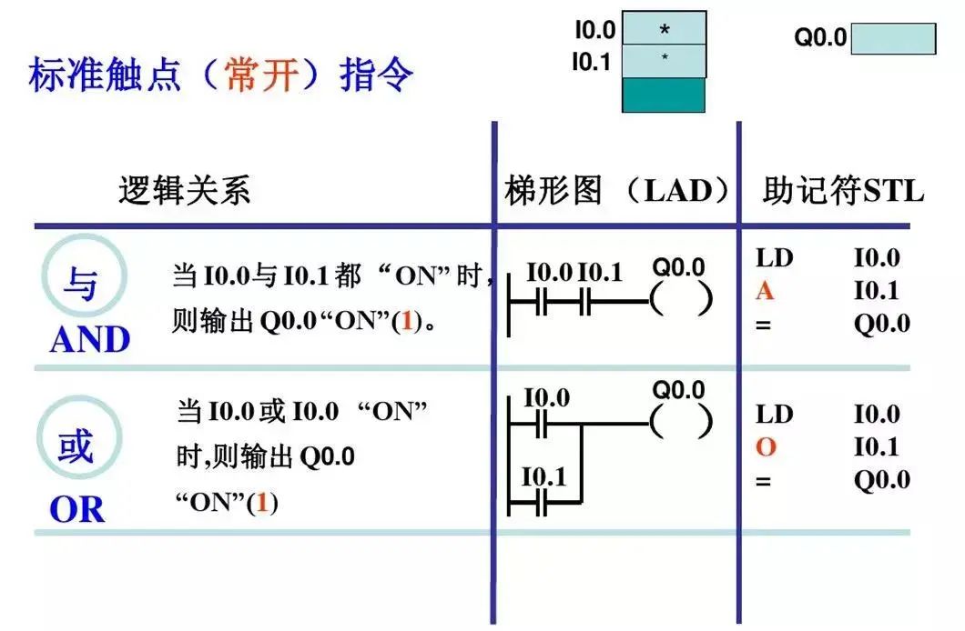
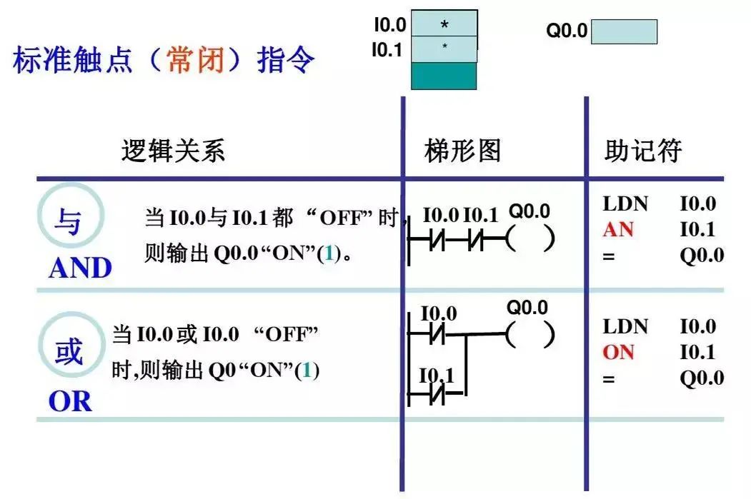
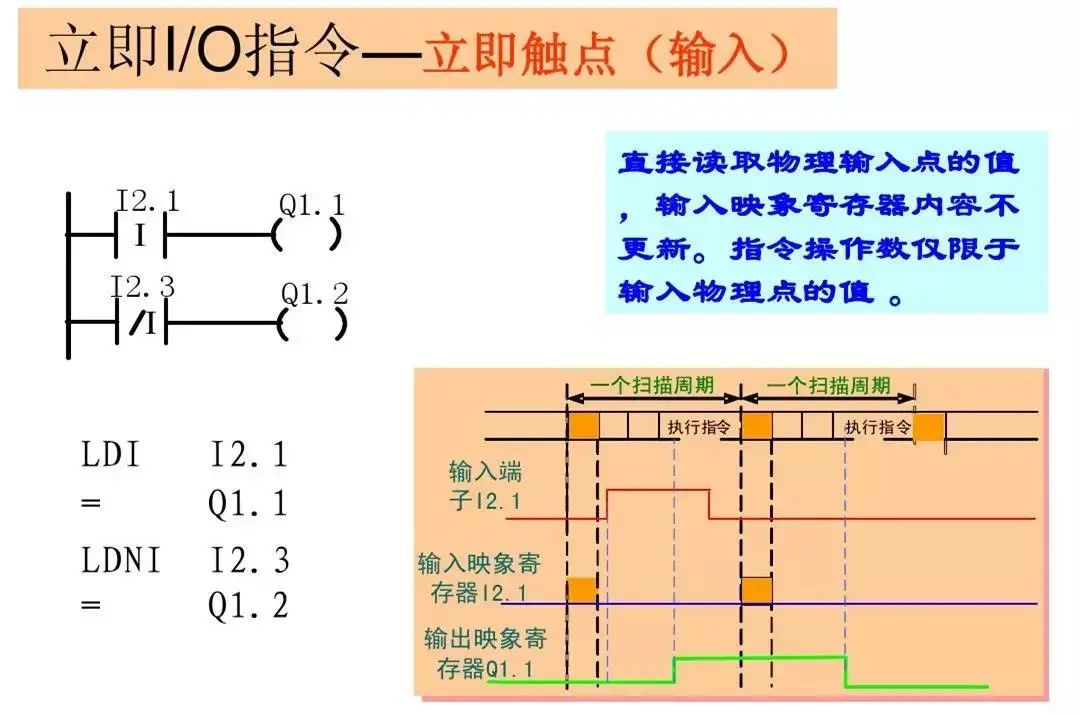
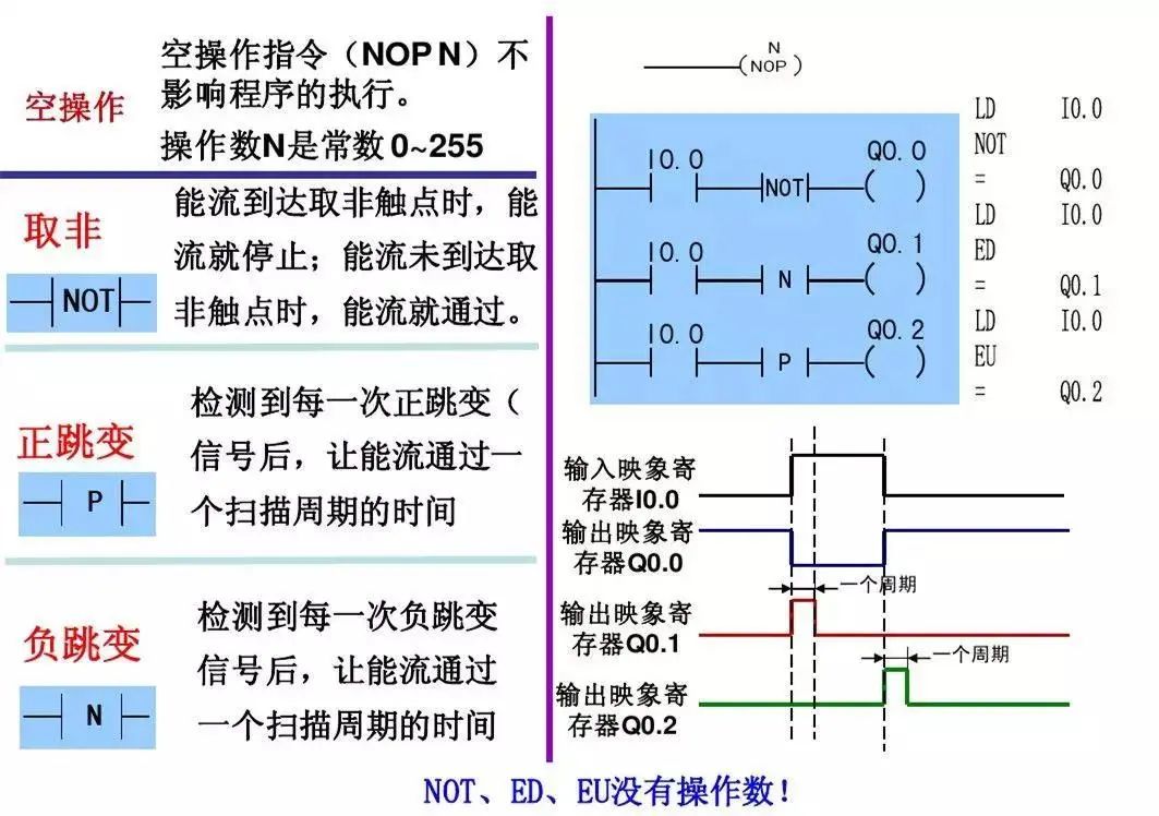
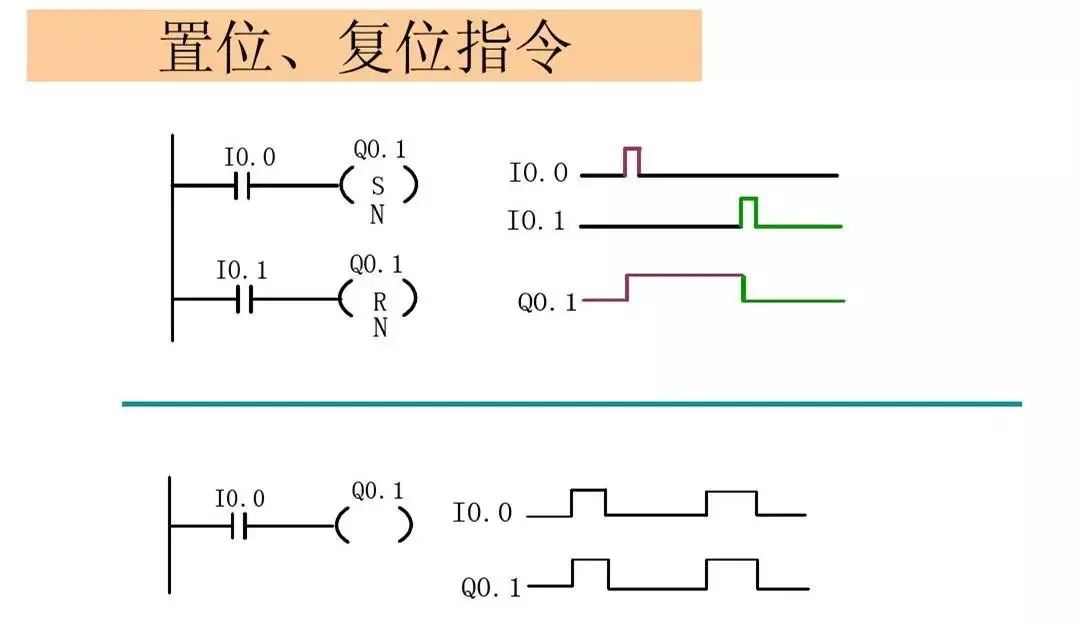
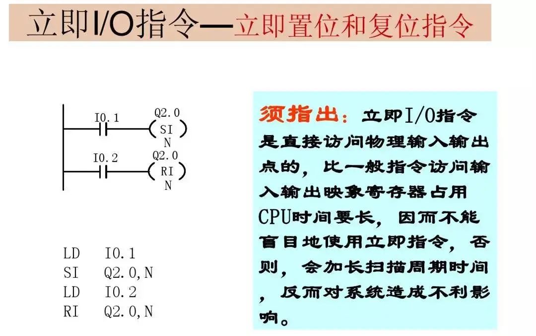
6. Output coils cannot directly drive field actuators but must drive through power devices on the I/O module. Basic logical instructions are primarily bit logical operations. In bit logical instructions, unless otherwise specified, the valid area for operands is: I, Q, M, SM, T, C, V, S, L, and the data type is BOOL. Contact and coil instructions are further divided into: standard instructions, immediate instructions, negation instructions, and positive (negative) edge instructions.