Click on the blue text above Talks Lab
Get more automotive network security information
Perface
Many solutions in the industry now contain multiple processors, whether hard processors like Arm A9, A53, or R5, soft cores like MicroBlaze, Arm Cortex-M1/M3, or a combination of both.
Arm Cortex-M1 is known as a soft core processor primarily because it offers greater flexibility in design and application. First, soft core processors can be customized as needed. For example, in hardware resource-limited situations, such as FPGA devices, Cortex-M1 can meet area budget requirements through optimized design. It adopts a three-stage 32-bit RISC processor architecture and uses efficient instruction sets, such as the Thumb-2 instruction set, allowing for higher performance under limited hardware resources. Secondly, soft core processors are also more flexible in application. They can be integrated into various hardware platforms, such as FPGA, ASIC, etc. At the same time, soft core processors can be programmed and controlled using different programming languages, making them adaptable to more application scenarios and needs. Due to their flexibility and adaptability, soft core processors are more popular in various application fields.
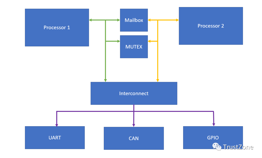
When we implement multi-processor solutions, we usually divide tasks among the available cores, utilizing each core to maximize its performance attributes. For instance, using MicroBlaze or Cortex cores in PL to perform dedicated real-time offloading tasks, while using hard-core application processors to execute higher-level functions.
If you have worked on complex SoC-related projects, you should be familiar with this, using a customized small core to assist the main processor in many tasks, or in multi-core SMP architectures, you will often see this kind of inter-core communication mechanism.
Of course, to correctly implement multi-processor solution applications, all processors in the solution need to be able to communicate and share available system resources safely and reliably.
This is where inter-processor communication (IPC) comes into play; if implemented correctly, it can achieve secure and reliable communication between processors, while also allowing multiple processors to share common resources, such as UART, without causing damaging conflicts.
Mailbox and MUTEX play different roles in our IPC solutions:
This letter being uppercase and lowercase suddenly makes me uncomfortable but I don't want to change it haha•Mailbox – allows for FIFO-based messaging methods for bidirectional communication between multiple processors.•MUTEX – implements a mutex, allowing processors to lock shared resources to prevent multiple accesses simultaneously.
Whether we use heterogeneous SoCs or FPGAs, mailbox and MUTEX are implemented in programmable logic (PL).
Heterogeneous SoC (System on Chip) processors are SoC processors that integrate multiple different architecture processing unit cores. For example, TI’s OMAP-L138 (DSP C674x + ARM9) and AM5708 (DSP C66x + ARM Cortex-A15) SoC processors, as well as Xilinx’s ZYNQ (ARM Cortex-A9 + Artix-7/Kintex-7 programmable logic architecture) SoC processors. Heterogeneous multi-core SoC processors combine the advantages of different types of processors. For instance, ARM processors are cheap and low-power, good at control operations and multimedia display; DSPs are born for digital signal processing, good at specialized algorithm calculations; FPGAs excel at high-speed, multi-channel data acquisition and signal transmission. Meanwhile, cores can quickly transmit and share data through various communication methods, allowing heterogeneous multi-core SoC processors to achieve a 1+1>2 effect.
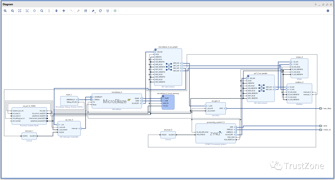
We can directly implement mailbox and MUTEX from the Xilinx IP library in our designs. Since both are used for communication between two processors, they each have two AXI inputs.
Using mailbox or MUTEX provides each processor with an AXI interface.
In this example, we will use Zynq to communicate and share resources with MicroBlaze in PL.
MicroBlaze will connect to the GPIO driving the LED.
To create a block diagram, we first need to add the Zynq processing system IP and run block automation to configure the Zynq for the selected board.
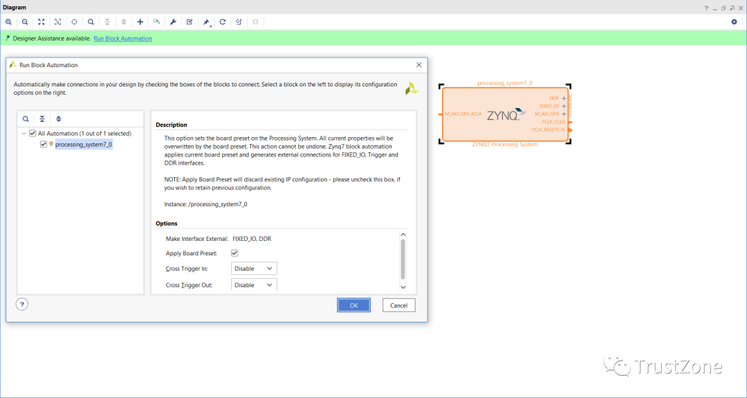
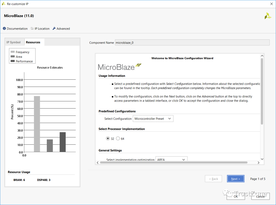
This is the added processing system. For the second one, use the IP directory to add MicroBlaze. Once the MicroBlaze IP appears in the block diagram, double-click to re-customize the IP, select the microcontroller preset, and keep all other options unchanged.
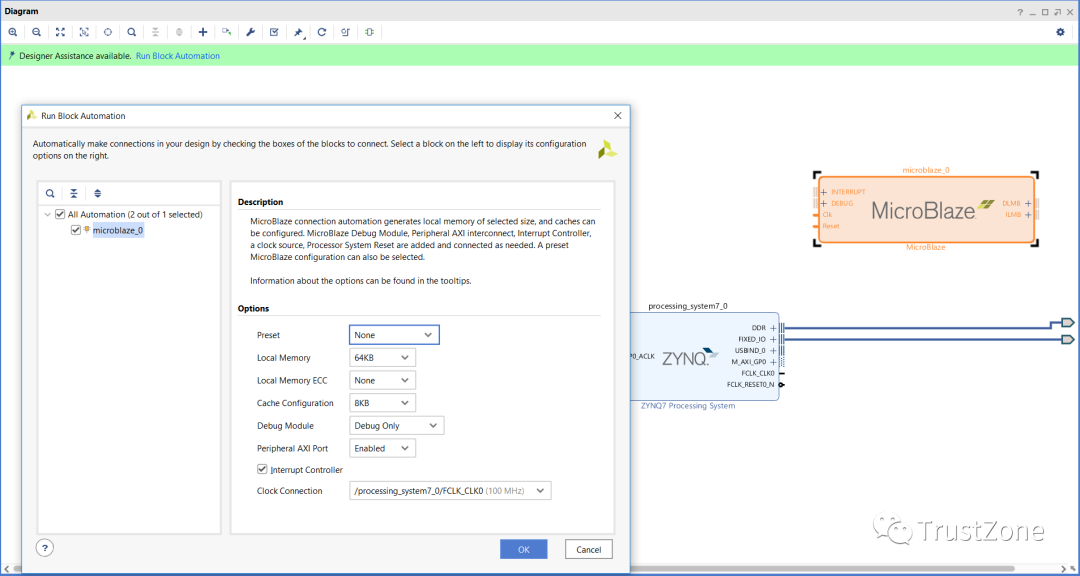
After configuring the MicroBlaze IP, the next step is to run its block automation to create the MicroBlaze solution. This will add to the block RAM, from which MicroBlaze will run and debug.
Now that we have our two processing system solutions, we are ready to add mailbox and MUTEX – both solutions can be added from the Xilinx IP directory.
Once completed, we can use the connection automation wizard to connect them to the AXI connections of the two processor systems.
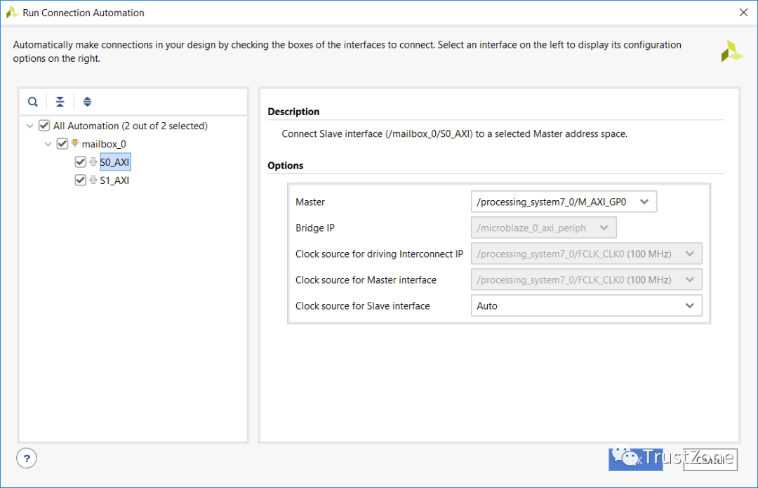
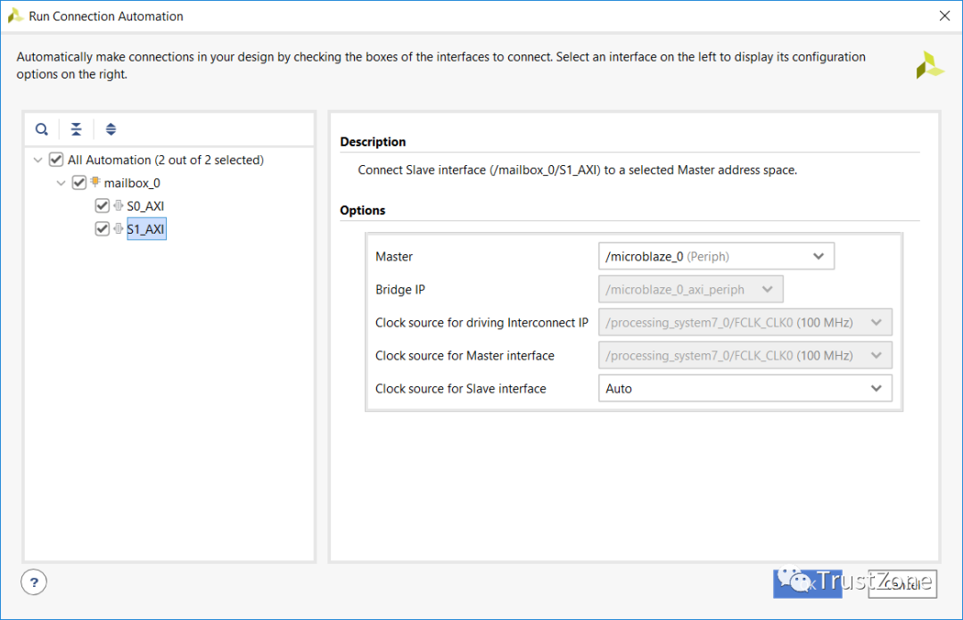
Mailbox uses FIFO to transmit messages, its depth can be configured by reusing the mailbox IP. To ensure effective processing of messages at the receiving processor, the mailbox can generate interrupts for the relevant processor when messages are queued.
Similar to mailbox, MUTEX is very similar, except it does not use FIFO but instead uses registers for each MUTEX to indicate the lock state. We can share up to 32 MUTEXes between up to 8 processors.
To prevent processors from accidentally or maliciously unlocking the mutex, use the CPU ID.
The completed block diagram should resemble the one below.
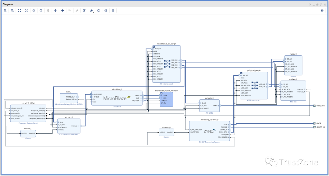
We can now build the hardware and export the design to SDK, preparing to write the software application.
MailBox
We have reviewed the hardware builds required to implement inter-processor communication (IPC) mailbox and mutex in Vivado.
Now, we will explore how to transfer data from one processor to another using the mailbox.
Remember, in this system, we are using one of the Zynq processing system (PS) A9 cores and MicroBlaze in programmable logic (PL).
Both processors are connected to the mailbox via AXI, so we can easily implement sending and receiving messages using the API provided in the board support package (BSP).
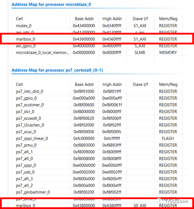
Exporting the design from Vivado to Xilinx SDK will import the hardware specifications into the SDK. Checking the HDF file in the hardware project will show the memory mapping of MicroBlaze and Cortex-A9.
After importing the hardware definition, the next step is to create two applications – one for Arm Cortex-A9 and one for MicroBlaze. When creating these applications, ensure to select the appropriate processor and enable the application to create a BSP as well.
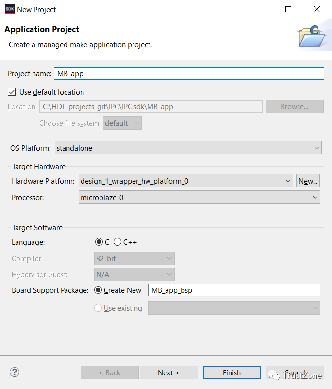
Once this is done, we should have the following in the SDK project explorer:
•A hardware platform describing the Vivado design – this serves as a reference hardware platform for all applications and BSPs.•Two board support packages – one for PS Arm A9 and one for MicroBlaze applications.•Two applications – one for PS Arm A9 and one for MicroBlaze.
In this application, MicroBlaze will report when it starts and runs, as well as the status of the LED being turned on or off.
To do this, we will use the mailbox API provided by the BSP, both offering the same API for use.
These files are included in the xmbox.h file, allowing us to initialize and configure the mailbox for use.
To read and write from the mailbox, there are several functions:
XMbox_Read ( XMbox * InstancePtr, u32 * BufferPtr, u32 RequestedBytes, u32 * BytesRecvdPtr)XMbox_ReadBlocking ( XMbox * InstancePtr, u32 * BufferPtr, u32 RequestedBytes )XMbox_Write(XMbox* InstancePtr,u32 * BufferPtr,u32 RequestedBytes, u32 * BytesSentPtr )XMbox_WriteBlocking ( XMbox * InstancePtr, u32 * BufferPtr, u32 RequestedBytes )In the above functions, the instance pointer references the mailbox declaration, and the buffer pointer points to the location where we store TX or RX data. While the requested bytes indicate the size of the transfer, the read and write functions also report the actual number of bytes sent or received, as this may differ from the requested byte count.
It is specifically noted that for all functions, the number of bytes sent or received should be a multiple of 4; if not, some padding is required. If the request is not a multiple of 4 bytes, an assertion will be generated.
Of course, blocking read and write will not report the actual number of bytes sent or received, as the function will effectively block until the requested number of bytes is sent or received.
In addition to send and receive functions, there are many internal management functions:
•Interrupt enable, status, and disable•Define send and receive interrupt FIFO thresholds•FFIO management and control, including checking empty and full, flushing and resetting. By using these functions, we can create simple applications for the Arm A9 core and MicroBlaze.
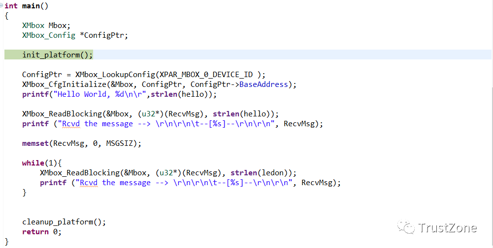
The A9 program is straightforward. Once the mailbox is initialized, it will loop forever waiting for messages from MicroBlaze, then print them out through the terminal.
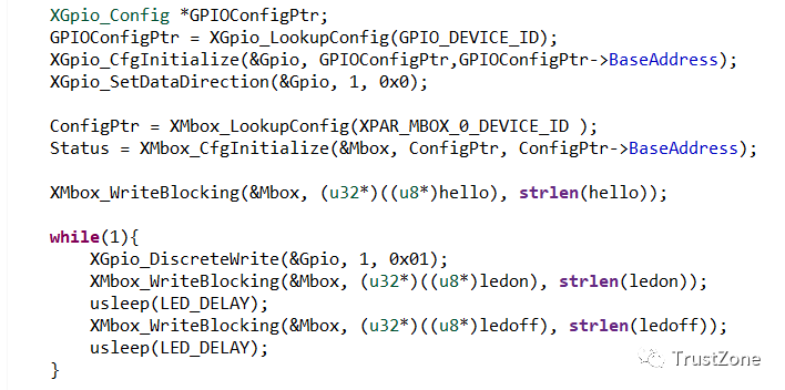
The MicroBlaze application is a bit more complex. It sends a message to the A9 core upon startup, and then every time it toggles the LED, it also sends a message regarding the LED state.
To run this on Zynq, we need to create a new debug configuration that downloads both processors. To ensure success in a multiprocessor environment, we need to consider the startup of both processors. In this debug configuration, select:
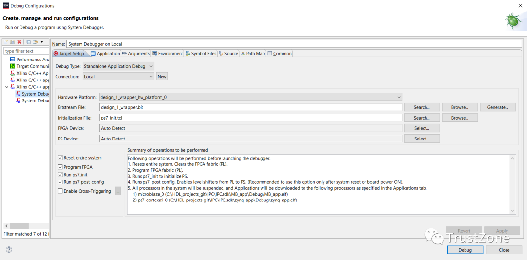
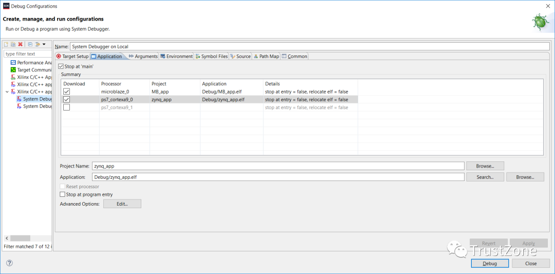
When the debug configuration runs, it will configure the device and download the applications for both processors. Then, both processors will pause at the entry point of main().
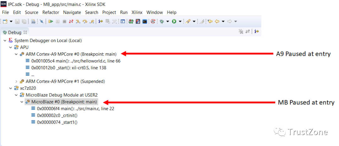
For this example application, please start the A9 processor first, followed by the MicroBlaze processor.
When executing the above example code, the following can be seen in the terminal window:
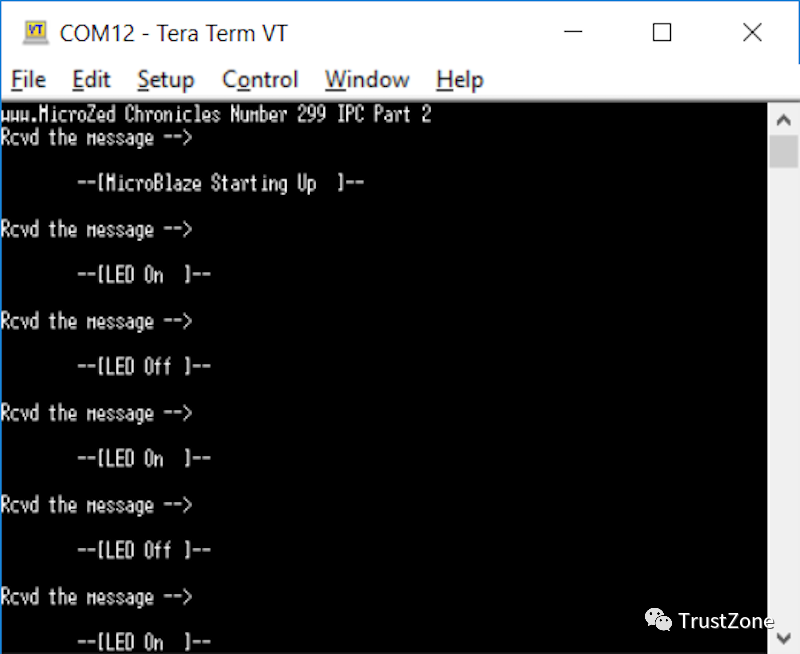
Both processors are communicating!
Next, we focus on the mutex.
MUTEX
When our device has multiple processors, multiple processors may want to share common resources (such as memory or UART) simultaneously. If access to these resources is uncontrolled, it can quickly and easily lead to corruption. For instance, serial port printing can get mixed up.
Mutual exclusion seems to be one of the simplest problems, and of course, a flag can be used, which both parties can test; if it is free, they claim access to the resource.
However, there is a problem where, during the time one processor tests and sets the flag, the other processor can also see the flag as free and start its locking process.
This is commonly referred to as a race condition, and other potential pitfalls surrounding mutual exclusion include deadlock and starvation. A processor cannot access a resource (starvation) or the system locks up because each processor is waiting for a different locking process to proceed (deadlock).
Whenever mutual exclusion is mentioned, the deadlock issue is often involved.
There are many solutions to address these issues, including using multiple flags. However, when considering anything beyond the simplest case, they start to become very complex, in short, they are not easy to scale.
The solution to the race condition is to ensure that the test and set operation is combined into one operation, meaning that if we test the mutex flag and it is free, it will be set.
This is exactly how Xilinx mutexes work, when we write to the mutex, if it is free, the processor will be allocated the resource.
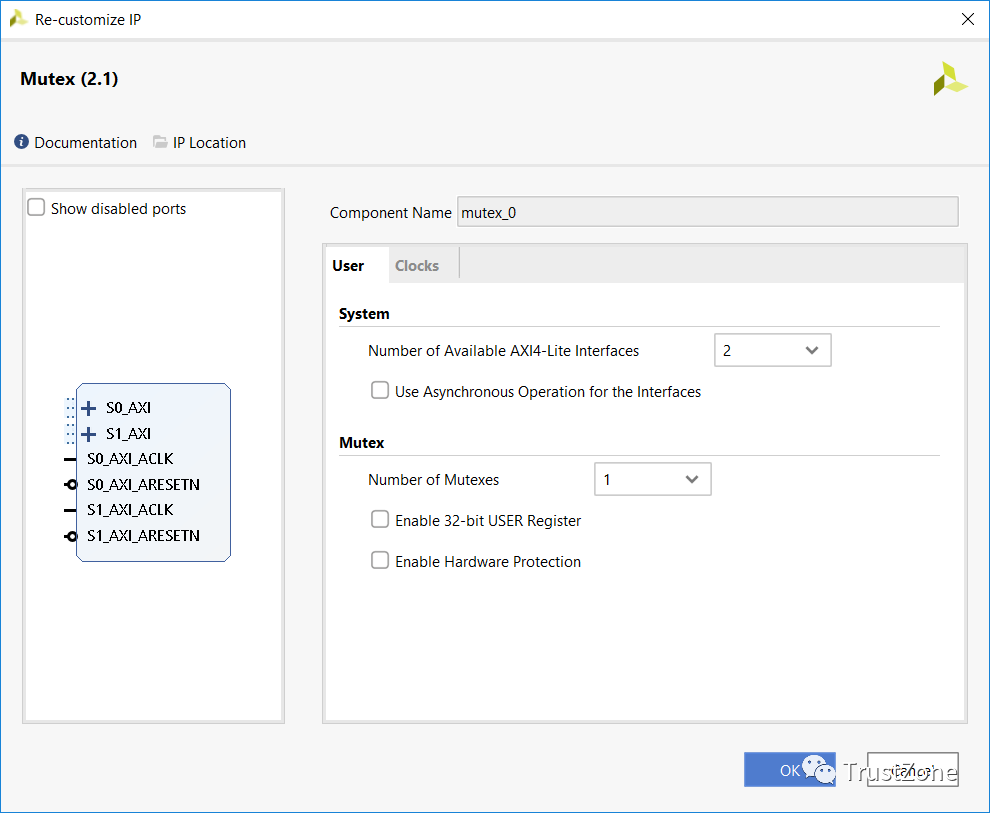
Designing mutexes in our hardware design is very simple; each processor has its own AXI interface. Since mutexes can support 1 to 8 processors, we can use only one interface when sharing resources between operating systems and tasks running on the same processor.
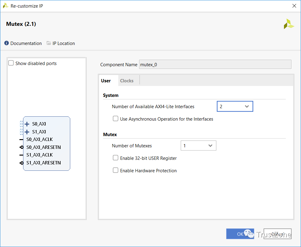
In one mutex instantiation, we can implement up to 32 mutexes. However, for this example, we only have one. When implementing the mutex, we can also enable hardware protection at the AXI level if we wish.
If we choose to enable this feature, the optional AXI HWID field is used to lock and unlock the mutex, preventing the CPU from spoofing the CPU ID and incorrectly unlocking it.
Each mutex also has an optional 32-bit register that can be used to share configuration data between processors if necessary.
When it comes to using mutexes in our software, we can use the Xmutex API (xmutex.h) provided by the board support package (BSP) for both processors. In this API, we will find function classes:
•Lifecycle management – initialization and status reporting•User registers – setting and clearing user registers•Mutex operations – functions to lock and unlock the mutex
Similar to the mailbox example we saw above, mutex operations provide blocking and non-blocking calls. The blocking call is provided by the function XMutex_Lock(), while the non-blocking function call is XMutex_Trylock().
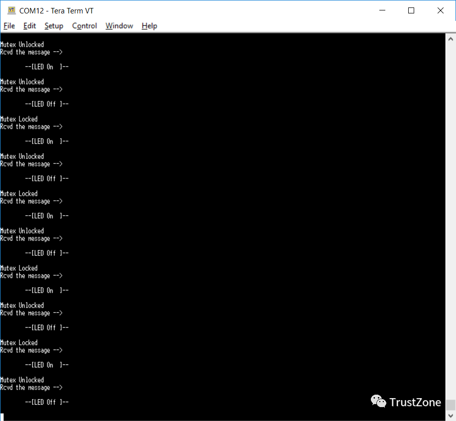
To demonstrate the application of the mutex, we will update our SW application so that the MicroBlaze application locks the mutex when setting the LED and unlocks the mutex when clearing the LED.
Then, the Zynq application will test the mutex and report whether it is set along with the LED status. A simple but effective example demonstrating how mutex functions work.
The code for both processors is as follows.
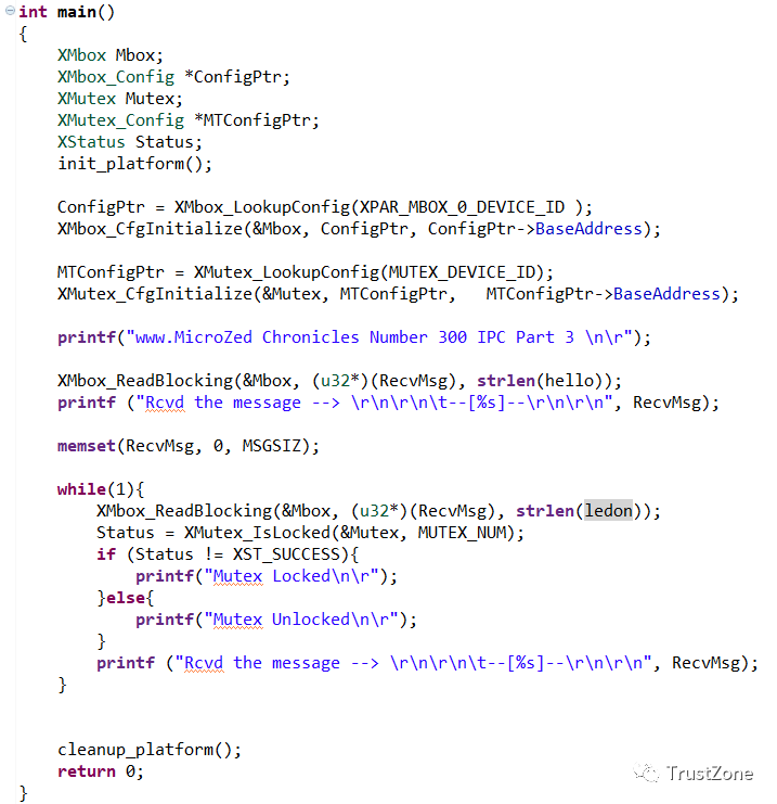
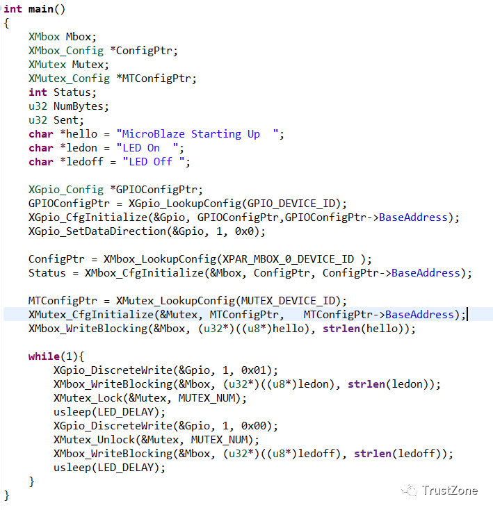
When running the application with the above code, the following can be observed in the terminal window. This indicates that MicroBlaze is locking and unlocking the mutex as expected when accessing the LED resource.
More Articles
Overview of Information Security for Intelligent Connected Vehicles
Huawei’s Cai Jianyong: Challenges and Thoughts on Digital Security and Functional Safety of Intelligent Connected Vehicles
Key Points of Automotive Data Compliance
Development and Testing Methods of On-Board Ethernet Technology
On-Board Ethernet Firewall Design
SOA: The Next Upgrade Direction for Vehicle Architecture
How Software