The common uses of PLCs include replacing relay logic control circuits in electrical control systems. For example, motor control, switchgear automatic transfer between municipal power supply, and control of backup generators, as well as process control DCS systems and building fire protection systems, etc. Generally, the water pressure control in high-rise residential buildings in urban areas is implemented using PLCs in conjunction with variable frequency drives to control water pumps.
More importantly, PLCs are used to build data exchange systems, which convert field buses into industrial Ethernet, enabling data exchange between field devices and back-end systems, as well as receiving and executing remote control commands, etc.
PLCs are widely used in industry, residential areas, national defense, transportation (subways, ports, civil aviation), banks, and mobile data centers.
I have designed thousands of PLC systems, among which notable projects include subway projects in over a dozen cities, air traffic control center projects in dozens of airports, multiple mobile base stations, and data center projects for several banks.
It is evident that the applications of PLCs are extensive.
—-Overview of PLC Hardware System—-
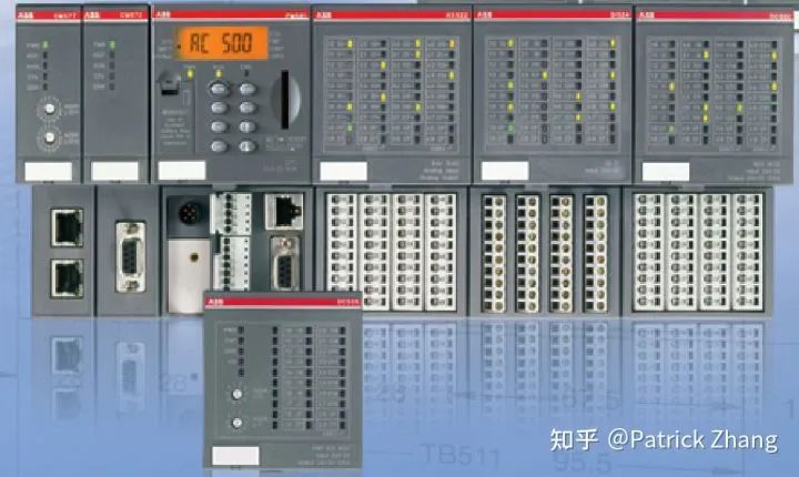
Figure 1: ABB’s AC500 Series PLC
On the left side of Figure 1 is the communication interface module, which enables data exchange between PLC communication data and network data. To the right is the main body of the PLC, namely the CPU module labeled “AC 500.” Further right are the digital input/output modules and analog input/output modules.
From this, we can see that a PLC is similar to a microcontroller system. In fact, a PLC is an intelligent microcontroller system, but its reliability and stability are very high, far exceeding that of general microcontrollers.
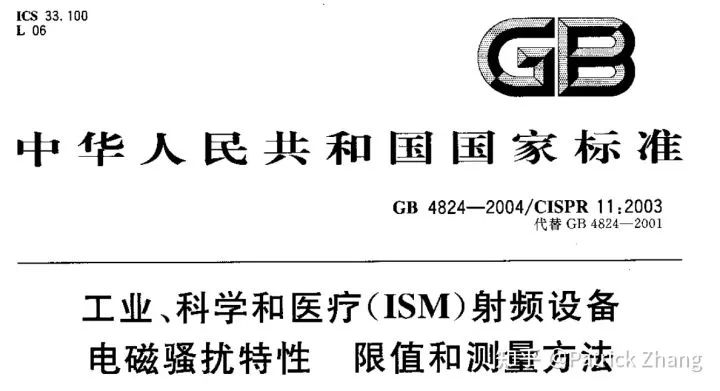
In industrial environments, electromagnetic interference is strong, so PLCs must meet national standards for electromagnetic interference. The relevant national standards for electromagnetic interference are as follows:
Figure 2: Measurement methods and requirements for electromagnetic interference under industrial conditions according to national standards
The hardware measures PLCs use to resist electromagnetic interference include power isolation, optical isolation for digital input interfaces, and optical isolation for analog inputs, among other measures. The electromagnetic interference on output interfaces is weaker, but certain measures also need to be taken, including OC gates and relay interfaces, etc.
To improve the reliability of PLCs, redundant configurations of master and slave PLCs are also implemented in important situations, as shown in the figure below:
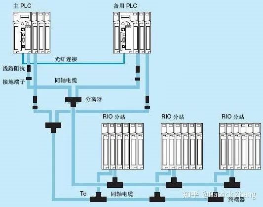
Figure 3: Redundancy measures for PLCs
Previously, we used industrial control computers as the data processing center in the power monitoring systems of substations, but industrial control computers faced issues such as power failures, hard disk failures, and weak resistance to electromagnetic interference, leading to their elimination in favor of PLCs as the data processing center. The following figure is an illustration from my book “Principles and Control Technologies of Low Voltage Complete Switchgear”:
Figure 4: The CCU in the figure is the communication management center built with PLCs
In Figure 4, there are systems using PLCs to execute low voltage incoming lines, bus coupling, and backup generator transfer systems, as well as PLC systems for data exchange.
—-PLC Software System—-
Anyone who has learned basic programming knows about loops. Once a program enters an infinite loop, it effectively freezes. The same applies to PLCs. Once a PLC enters an infinite loop, its interfaces will reset, and controlled quantities will face serious issues. Therefore, PLC program statements are executed sequentially, running until the last statement before returning, preventing infinite loops. Even for transfer instructions, as long as the transfer condition is met, it will transfer; otherwise, it will skip the transfer segment and continue execution.
This is one reason why PLC software systems have high reliability.
Let’s take a look at the figure below:
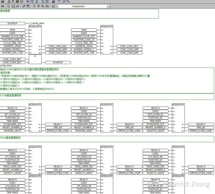
Figure 5: Modular programming language for PLCs
Figure 5 is an excerpt from the PLC program of the Beijing subway project.
PLC program formats come in two types: one is ladder diagram format, and the other is modular programming language format. For more complex PLC programs, modular programming language is generally used for writing. Regardless of whether it is ladder diagrams or modular programming languages, they must comply with the requirements of the International Electrotechnical Commission IEC61131-3 standard.
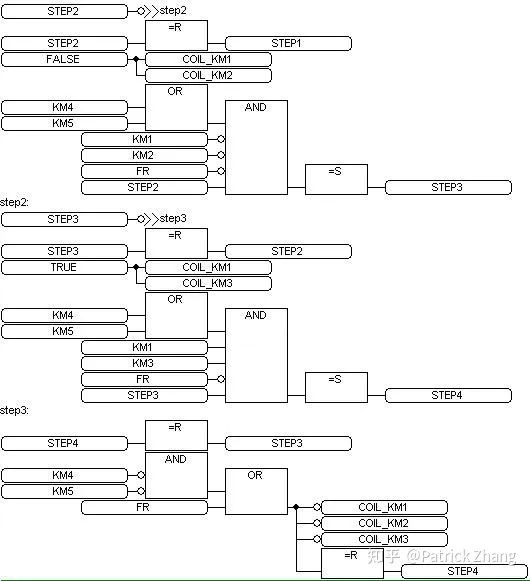
The following figure shows a program used to control a motor for star-delta conversion:
Figure 6: Partial PLC program for motor star-delta conversion
In Figure 6, STEP2 and STEP3 are the transfer program segments. If the conditions are not met, the program will skip the transfer segment and execute.
The most interesting part is the PID program module of the PLC, which is very valuable for use.
—-Advice for Everyone—-
When learning PLC technology, most start with ladder diagrams. In fact, learning PLC initially often involves controlling traffic lights at intersections, etc. However, true PLC technology is far beyond this; once you have worked on a project, your understanding of PLCs will significantly improve.
END
【Recommended Books】
Teacher Zhang Baifan has published two books:
Recommendations for beginners in PLC:
Click the link to go to the book purchase page https://j.youzan.com/08mhLe

Follow our video account for more video tutorials