Click the blue text to follow us

1. Overview of the Microcontroller Instruction System
Programming Language: A set of rules for writing programs.


Three Types of Programming Languages:
Machine Language, Assembly Language, High-Level Language
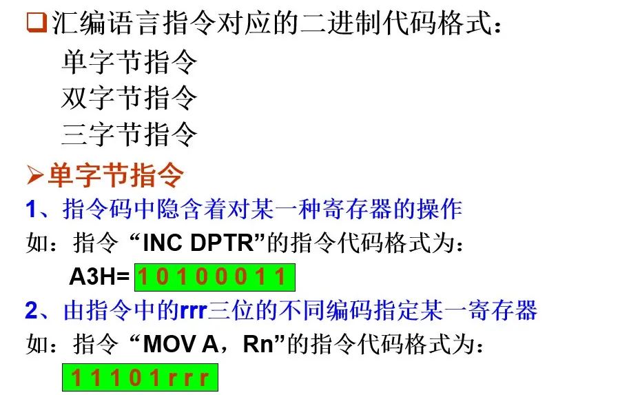
Machine Language: A language represented by binary codes for each instruction, directly recognizable and executable by the computer.
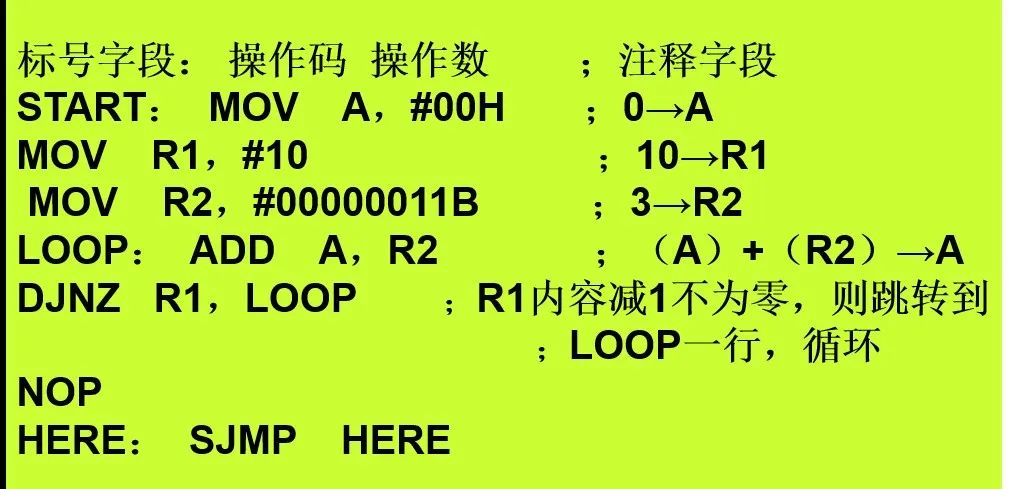
Assembly Language: A programming language that represents instructions using mnemonics, symbols, and numbers. It corresponds one-to-one with machine language instructions.
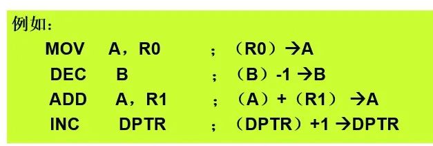
(1)Rn(n=0~7) The currently selected working registers R0~R7
(2)Ri(i=0,1) The currently selected registers R0, R1 used as address pointers
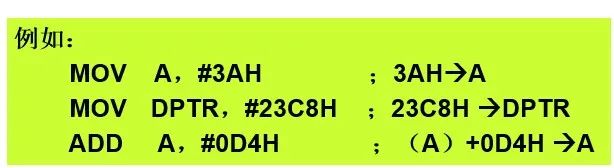
(3)#data 8bit immediate value
(4)#data16 16bit immediate value
For example: MOV DPTR, #data16
(5)direct 8bit direct address of internal RAM unit (including SFR)
For example: MOV direct, #data ; #data→direct
(6)addr11
11bit destination address, used in ACALL and AJMP instructions
(7)addr16
16bit destination address, used in LCALL and LJMP instructions
(8)rel 8-bit address offset in two’s complement form
(9) bit bit address for direct addressing of internal RAM or SFR
(10)@ Symbol representing indirect addressing register
(11) / Bitwise NOT operation, for example: ANL C, /P1.2
(12)(×) Content in “×” is data; × is the address
(13)(( ×)) Content in the indirect addressing unit of “×”, the content in “×” is the address
For example: if the data in cell 58H is 36H, the content of R0 is 58H
INC 58H ; (58H)+1→ 58H
DEC @R0 ; ( (R0) )-1 → (R0)
(14)→ Indicates that the content on the left side of the arrow is transferred to the unit on the right side of the arrow
4. The number of bytes and cycles of instructions

2. Addressing Modes of the 80C51 Microcontroller

3. Register Addressing
The operand is in a certain register.
The registers used can be: R0~R7, A, B, DPTR, etc.
7. Bit Addressing
Bit addressing: The operand of the instruction using bit addressing is a certain bit in an 8-bit binary number, and the bit address is given in the instruction. The bit address is represented in the instruction using bit.
For example: CLR bit
MOV ACC.0, 11H ; ACC.0←(11H)
Two methods of representing bit addresses:
Directly use the bit address, such as D3H;
Directly use the register name plus bit number, such as PSW.3.
Bit addressing area:
The 128 bits in the 16 units of internal RAM from 20H to 2FH;
Byte addresses that can be divided by 8 in SFR.

3. Introduction to Instruction Classification of the 80C51 Microcontroller
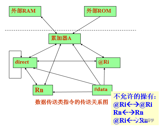
Data Transmission Instructions
Internal RAM data transfer instruction group
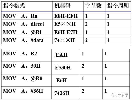
(1) Instructions with A as the destination operand (4 instructions)
MOV A, Rn ; (Rn)→A
MOV A, direct ; (direct)→A
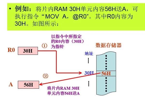
MOV A, @Ri ; ((Ri))→A
MOV A, #data ; data→A
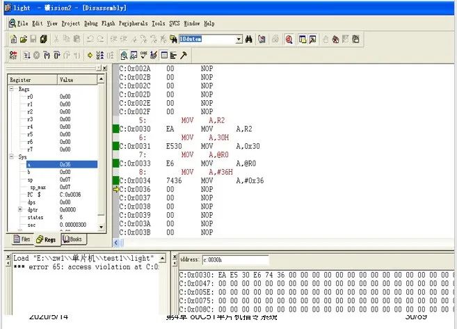
For example: MOV A, R2
MOV A, 30H
MOV A, @R0
MOV A, #36H
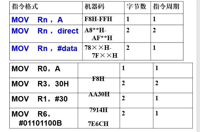
(2) Instructions with Rn as the destination operand (3 instructions)
MOV Rn, A ; (Rn)→ Rn
MOV Rn, direct ; (direct)→ Rn
MOV Rn, #data ; data→ Rn
For example: MOV R0, A
MOV R3, 30H
MOV R7, #36H
MOV R1, #30
MOV R6, #01101100B
MOV direct, A ; (A)→direct
MOV direct, Rn ; (Rn)→direct
MOV direct, direct ; (source direct)→ destination direct
MOV direct, @Ri ; ((Ri))→direct
MOV direct, #data ; data→direct
For example: MOV 30H, A
MOV P1, R2
MOV 38H, 60H
MOV TL0, @R1
MOV 58H, #36H
(4) Instructions with indirect address as the destination operand (3 instructions)
MOV @Ri, A ; (A)→(Ri)
MOV @Ri, direct ; (direct)→(Ri)
MOV @Ri, #data ; data→(Ri)
For example: MOV @R0, A
MOV @R1, 36H
MOV @R1, #48
MOV @R0, #0D6H
(5) Sixteen-bit data transfer instruction (1 instruction)
MOV DPTR, #data16 ; dataH→DPH, dataL→DPL
For example: MOV DPTR, #2368H
MOV DPTR, #35326
1. Data transfer instructions between accumulator A and external RAM (4 instructions)
MOVX A, @Ri ; ((Ri))→A, and set /RD=0
MOVX A, @DPTR ; ((DPTR))→A, and set /RD=0
MOVX @Ri, A ; (A)à(Ri), and set /WR=0
MOVX @DPTR, A ; (A)à(DPTR), and set /WR=0
Note:
2. Program memory data transfer instruction group (2 instructions)
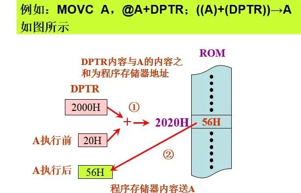
MOVC A, @A+DPTR ; ((A)+(DPTR))→A
MOVC A, @A+PC ; ((A)+(PC))→A
• Program memory can only be read, not written;
• These two instructions are commonly used for table lookup operations, both are single-byte instructions;
• For the instruction based on DPTR, the addressing range is the entire ROM’s 64KB space; for the instruction based on PC, it can only read a certain unit within 256 address units starting from the current MOVC instruction, because the PC value is relatively fixed during program execution.
3. Stack operation instructions (2 instructions)
PUSH direct ; first (SP)+1→SP, then (direct)→(SP)
POP direct ; first ((SP)) →direct, then (SP)-1→SP
For example: PUSH 0E0H ; actually (A)→(SP)
POP 05H ; actually ((SP))→R5
Note: The operand must be a direct address, and cannot use register names.


4. Exchange Instructions (5 instructions)
(1) Full byte exchange instructions
XCH A, Rn ; (A)← →(Rn)
XCH A, direct ; (A)← →(direct)
XCH A, @Ri ; (A)← →(((Ri)))
(2) Half-byte exchange instructions
Low half-byte exchange instructions
XCHD A, @Ri ; (A0~3)← →(((Ri)0~3))
For example: if (A)=36H, (R1)=65H, (65H)=42H
XCHD A, @R1 ;
Execution result: (A)=32H, (65H)=46H
SWAP A ; (A0~3)← →(A4~7)
For example: if (A)=36H
SWAP A ; (A)=63H


Utilize English abbreviations to memorize instruction functions
For example: MOV is the abbreviation for MOVE, the general format of the instruction is:
MOV
Illegal instructions cannot be used for programming
Note that the following instructions are illegal instructions:
MOV Rn, Rn
MOV @Ri, @Ri
MOV Rn, @Ri
MOV #data, A


1. Grasp the similarities of various instructions for comparative learning
2. Pay attention to the effect of instruction execution on the Program Status Word (PSW)
3. Be aware of the restrictions on using instructions
Logical Operation Instructions
Includes AND, OR, XOR, clear, complement, shift, etc. These instructions generally do not affect the flags CY, AC, and OV, with a total of 24 instructions.
1. Clear accumulator A to 0 and complement instructions (2 instructions)
(1) Clear accumulator A instruction
CLR A ; 0 → A
Explanation: Only affects flag P.
(2) Complement accumulator A instruction (bitwise complement)
CPL A ; (/A) →A, equivalent to 0FFH – A→ A
Explanation: Does not affect flags.
For example: (A)=56H CPL A ; Result is 0A9H
2. Shift instructions (4 instructions)
(1) Accumulator A rotates left
RL A ;
(2) Accumulator A rotates right
RR A ;
(3) Accumulator A rotates left with carry
RLC A ;
(4) Accumulator A rotates right with carry
RRC A ;
Explanation:
(1) Each instruction only moves one bit at a time;
(2) Left shifting one bit is equivalent to multiplying by 2; right shifting one bit is equivalent to dividing by 2;
(3) Carry bit shifting affects flags CY and P.
3. Logical AND instructions (6 instructions)
ANL A, Rn ; (A)∧(Rn)→A
ANL A, direct ; (A)∧(direct)→A
ANL A, @Ri ; (A)∧((Ri))→A
ANL A, #data ; (A)∧#data →A
ANL direct, A ; (direct)∧(A)→direct
ANL direct, #data ; (direct)∧#data →direct
Explanation:
-
The destination operand can only be A or direct;
-
The first four instructions only affect flag P; the last two do not affect flags;
-
Logical AND operation mainly serves as a masking function, allowing certain bits to be ANDed with “0”, while others are ANDed with “1”.
4. Logical OR instructions (6 instructions)
ORL A, Rn ; (A)∨(Rn)→A
ORL A, direct ; (A)∨(direct)→A
ORL A, @Ri ; (A)∨((Ri))→A
ORL A, #data ; (A)∨#data→A
ORL direct, A ; (direct)∨(A)→direct
ORL direct, #data ; (direct)∨#data→direct
Explanation:
(1) The destination operand can only be A or direct;
(2) The first four instructions only affect flag P; the last two do not affect flags.
(3) OR operation is often used to set certain bits to 1, commonly serving a “merging function”.
XRL A, Rn ; (A)∨(Rn)→A
XRL A, direct ; (A)∨(direct)→A
XRL A, @Ri ; (A)∨((Ri))→A
XRL A, #data ; (A)∨#data→A
XRL direct, A ; (direct)∨(A)→direct
XRL direct, #data ; (direct)∨#data→direct
Explanation:
(1) The destination operand can only be A or direct;
(2) The first four instructions only affect flag P; the last two do not affect flags.
(3) XOR operation is commonly used to complement certain bits. XORing a register’s value with 0FFH can achieve the function of complementing that register.
Includes bit variable transfer, logical operations, control transfer, etc., with a total of 17 instructions, divided into 4 small categories.Only some instructions affect the CY flag.
Methods of representing bit addresses:
Directly use the bit address, such as: D4H
Use special function register name plus bit number, such as: PSW.4
Use bit name, such as: RS1
Use named bit addresses defined by bit, such as: SUB bit RS1, MM bit 02H
1. Bit data transfer instructions (2 instructions)
MOV C, bit ; (bit)→C
MOV bit, C ; (C)→bit
For example: MOV C, TR0
MOV 08H, C ; Temporarily store CY content
MOV C, 10H ; Send 10H bit to CY
MOV 5AH, C ; Send CY content to 5AH
MOV C, 20H ; Restore CY content
2. Bit modification instructions (6 instructions)
(1) Bit clear to 0 instruction
CLR C ; 0→C
CLR bit ; 0→(bit)
For example: CLR TR0
(2) Bit set to 1 instruction
SETB C ; 1→C
SETB bit ; 1→(bit)
For example: SETB TR0
SETB 06H ;
(3) Bit complement instruction
CPL C ; (/C)→C
CPL bit ; (/bit)→bit
For example: CPL TR0
CPL EA
3. Bit logical operation instructions (4 instructions)
(1) Bit logical AND instruction
ANL C, bit ; (C)∧(bit)→C
ANL C, /bit ; (C)∧(/bit)→C
For example: ANL C, P1.0
ANL C, /P1.2
(2) Bit logical OR instruction
ORL C, bit ; (C)∨(bit)→C
ORL C, /bit ; (C)∨(/bit)→C
For example: ORL C, P1.0
ORL C, /P1.2
4. Bit conditional transfer instructions (5 instructions)
(1) Conditional transfer instructions based on C value
JC rel ; (PC)+2→PC
; If (C)=1, then (PC)+rel→PC
; If (C)=0, then continue executing downwards
JNC rel ; (PC)+2→PC
; If (C)=0, then (PC)+rel→PC
; If (C)=1, then continue executing downwards
For example: JC NEXT1
JNC FIRST
(2) Conditional transfer instructions based on bit value
JB bit, rel ; (PC)+3→PC
; If (bit)=1, then (PC)+rel→PC
; If (bit)=0, then continue executing downwards
JNB bit, rel ; (PC)+3→PC
; If (bit)=0, then (PC)+rel→PC
; If (bit)=1, then continue executing downwards
For example: JB BA, NEXT1
JNB TI, $
(3) Conditional transfer instructions that clear bit value to 0
JBC bit, rel ; (PC)+3→PC
; If (bit)=1, then (PC)+rel→PC, 0→bit
; If (bit)=0, then continue executing downwards


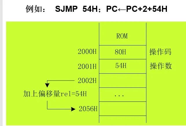
1. Clarify the limitations of relative transfer instructions
Relative transfer instructions fall into two categories: One category is relative transfer instructions within a 2KB range (such as AJMP addr11 instructions), where the target transfer address generated after instruction execution must be within the same 2KB range as the address in the program counter PC; the other category includes transfer instructions containing rel in the instruction code.
2. Calling instructions include long calling instructions and short calling instructions.
Long calling instructions can call any subroutine within a 64KB range;
Short calling instructions can only call subroutines whose starting addresses are within the same 2KB range as the starting address of the short calling instruction.
3. Calling instructions and return instructions must be used in pairs.

Long press the image to follow
Discover more exciting content
WeChat ID : Mechanical-knowledge