In the design, application, and selection process of fire automatic alarm systems, we often pay attention to the appearance, sensitivity, stability, and intelligence level of fire detectors, as well as the performance, interface, and functions of the control panel. However, during actual engineering construction, there are some seemingly simple issues that deserve our close attention.
#1Bus Fire Alarm Control System Voltage Drop Issues
Have you encountered the following problem during the debugging of a bus-based fire alarm control system:
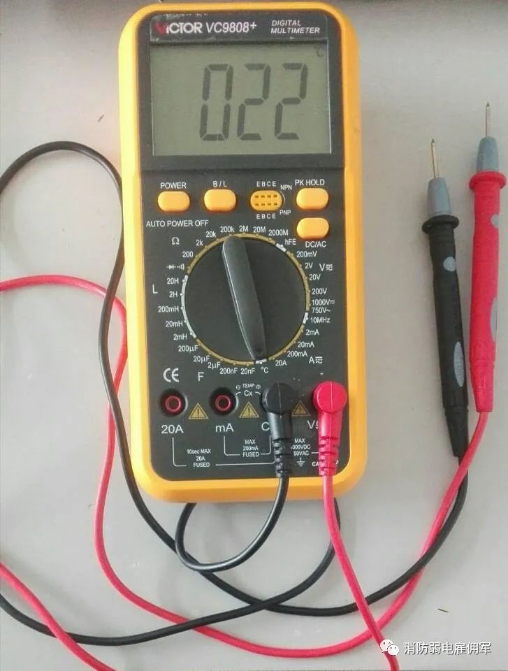
The fire alarm controller has issued a control command, and the control module has activated, but some external control devices such as smoke exhaust valves and air supply outlets fail to operate. We used a multimeter on-site to monitor the DC24V input voltage of the control module and found that before the fire alarm controller issued the control command, the voltage remained unchanged. However, once the control command was issued, the voltage dropped by several volts.
What is the reason for this?
Both the fire automatic alarm circuit and the fire linkage control circuit have voltage drop issues. This is generally not evident in small systems, but in projects with larger building areas and longer lines, this problem becomes more pronounced. This is often overlooked by construction personnel, and when the problem is exposed, they seek various remedial measures, which not only takes time and effort but is also difficult to resolve completely.
The voltage drop issue is mainly caused by the following two reasons.
1) Internal Resistance of Wires
Wires have resistance. The resistance value is proportional to the length of the line and inversely proportional to the cross-sectional area of the wire. Additionally, some manufacturers produce low-quality wires, which inadvertently increase the resistance.
2) Contact Resistance
Various addressing units such as smoke detectors, temperature detectors, input modules, output modules, and short circuit isolators are connected in the bus. Over time, the exposed terminals in the air will develop an oxide layer, leading to contact resistance. The more addressing units connected, the greater the contact resistance.
We collectively refer to the internal resistance of wires and contact resistance as line internal resistance. It is precisely due to the existence of line internal resistance that the voltage drop issue occurs across the load in the circuit. According to Ohm’s law, the voltage drop value is proportional to the ratio of line internal resistance to load resistance. Therefore, to reduce the voltage drop, we must find ways to reduce the ratio of line internal resistance to load resistance.
The bus-based fire alarm control system generally has three types of buses: loop bus, power bus, and network bus. The loop bus refers to the connection between the fire alarm controller and various addressing units; the power bus refers to the lines that provide DC24V to control modules, floor displays, etc.; the network bus refers to the communication bus between the fire alarm central controller, slave controllers, and floor displays in the system.
Compared to the power bus, the voltage drop issues in the loop bus and network bus are less common. Taking the loop bus as an example: various alarm device manufacturers pay great attention to this issue, and they have clear requirements regarding the maximum load of the loop and the length and diameter of the loop. Therefore, as long as the manufacturer’s wiring requirements are met, there should be no issues.
The voltage drop issue has a significant impact, generally occurring in the power bus, primarily due to the large current drawn by electromagnetic valve type linkage devices.
Fire shutter doors, fans, and pumps are all controlled via intermediate relays. The resistance value of the relays typically exceeds 500 ohms, and the operating current is already much larger than the working current of the addressing units in the loop bus, but this is not the main cause of the voltage drop issue. Electromagnetic valve type linkage devices, such as smoke exhaust valves, air supply outlets, and gas extinguishing system starting cylinders, are the real “power consumers”. The resistance of an electromagnetic valve is generally 36 ohms, with an operating current of about 0.65 amperes. Such a large operating current is sufficient to create a significant voltage drop due to line internal resistance.
Here are a few engineering examples to illustrate the adverse effects of voltage drop in projects.
In the Huainan XXXX project, there are two smoke exhaust outlets, two air supply outlets, two sound and light alarms, and one strong electricity switch on each floor. After confirming a fire, it is necessary to open the air supply outlets on the current floor and the floor above and below, requiring at least 12 outlets to be linked. The resistance of one electromagnetic valve is 36 ohms, and with 12 outlets connected in parallel, the total resistance is 3 ohms. The building is 30 stories high, with a floor height of 3 meters, resulting in a vertical height of 90 meters. According to the copper core wire used in this fire protection project, with a cross-section of 2.5mm2, we can calculate the resistance for a length of 90 meters using R=ρL/s. The resistance for this 90-meter length of 2.5mm2 copper core wire is 0.714 ohms. According to Ohm’s law, U_device=24/(3+0.714)*3=19.3V, while the device’s starting voltage is 20V. Without considering the power consumption of the strong electricity switch and sound-light alarm, the device cannot start.
In the Huainan XXXX project, the fire hydrant system uses a dry system, where each pipe has a large electromagnetic valve controlling the water flow direction. If different floor fire hydrants alarm simultaneously while in the automatic state, the electromagnetic valves on different floors will activate simultaneously. Due to the excessive current, even one electromagnetic valve cannot start, the situation is the same as above, caused by voltage drop.
Understanding the adverse effects of voltage drop, how can we effectively prevent similar issues from occurring? I have summarized the following points from the site.
1) Implement Time-Based Control for Controlled Devices
Time-based control can reduce the number of devices that need to be controlled at the same time. Devices that require large current, such as electromagnetic valves, only need pulse signals instead of continuous power supply. This way, the number of external control devices connected in parallel on the power bus decreases, which can mitigate the impact of line internal resistance. Even for devices like sound-light alarms that require continuous power, time-based starting is effective, as the starting current is large but reduces significantly after the device starts, alleviating the issue of excessive current at the same time. There are two methods to achieve time-based control: one is software programming, using the delay output function of the fire alarm itself; the other is hardware connection, interconnecting similar external control devices through their interlock control terminals to drive them one by one.
In the previous engineering example, we can implement such methods to reduce voltage drop, such as activating one air valve every 5 seconds; connecting all air supply outlets in series, using one control module to control them, so that the subsequent air supply outlet only activates after the previous one closes. This significantly reduces the number of devices driven by the alarm.
If all external control devices can achieve time-based control through software programming, there is no need for hardware connections. For example, our company’s Yi’ai brand devices have excellent delay functions, which can meet the needs of a 50,000 square meter project in practical engineering, such as the Hefei Lvdou Shopping Mall and Tianjin Jinlian Building. However, some manufacturers’ controllers have less effective delay functions. Delay control affects the operating speed of the controller. Therefore, hardware connections are also a factor we need to consider.
2) Install Multiple DC24V Power Bus Main Lines
In engineering design, it is essential to consider laying multiple main lines, which can reduce the number of control modules in the lines, thereby reducing contact resistance. Additionally, it can avoid a single power bus winding around, which greatly helps reduce line length. A significant number of personnel believe that when devices fail to start or operate normally, it is due to insufficient power supply, whereas in reality, most issues are caused by voltage drop. In this case, the above methods yield better results. For instance, in the Qingdao Vancouver Garden project, 186 combustible gas detectors were used, but the detectors could not function correctly. In reality, our external power output current is 10A, which fully meets the load; the issue was caused by voltage drop. Only by laying multiple power lines could the problem be resolved. After implementing multiple wiring, the system operated normally.
3) Use Larger Wire Gauges
In design, some designers tend to overlook the wire gauge of the DC24V power supply lines and the matching issue with the selected electrical devices—especially the wire gauge of control lines for various electric control air valves. Some designers do not pay attention to the gauge of these lines and do not consider how many devices are on these lines and their instantaneous operating currents. Often, when a fire occurs, a series of linked devices need to open or close within a corresponding timeframe. If the power supply cannot keep up, the relays controlling these devices cannot function correctly, leading not only to the failure to interlink related fire control devices but also potentially damaging the devices. This issue is particularly pronounced in basements with numerous linked devices.
Below, we will calculate the appropriate wire gauge for the power lines on a standard floor. For instance, on each standard floor, there is one smoke exhaust outlet and one positive pressure outlet, and after confirming a fire, it is necessary to open the air supply outlets on the current floor and the floors above and below, requiring at least 6 outlets to be linked. The nominal operating current for these outlets generally ranges from 0.5 to 2 amperes, with actual measured currents mostly around 1 ampere. Therefore, to be safe, we take 1 ampere as the value, and the valve’s starting voltage cannot be lower than 20V. Thus, R_line=(U-U_valve)/I_start=(24-20)/(6*1)=0.67, indicating that the resistance of the DC power supply wire in the vertical shaft on the standard floor should not exceed 0.67.
Assuming the building is 30 stories high, with a floor height of 3 meters, resulting in a vertical height of 90 meters, we can use R=ρL/s to determine that if we use copper core wire with a cross-section of 2.5mm2, the resistance for 90 meters would be 0.714. Using 4 mm2 copper core wire, the resistance would be 0.464. Therefore, we should use copper core wire with a gauge of 4 mm2 or larger. This demonstrates that our estimates are often inaccurate. In basements with even more linked devices, we must perform more detailed calculations to determine the appropriate wire gauge for the power lines.
4) Soldering Connections
This can help reduce both the internal resistance of wires and contact resistance.
5) Place DC24V Power Boxes On-Site
This is meant to compensate for the inherent deficiencies of the project and is a last resort. However, two points must be noted: first, the on-site AC220V supply must be a dedicated fire protection power supply, and second, the power supply can be turned on or off within the fire control center.
Fire alarm devices, when they leave the manufacturer, have only completed the first step. Even the best-quality devices rely heavily on installation quality for their operational status. This requires us to consider comprehensively before construction and ensure quality during construction. Issues like voltage drop can be avoided if we consider them at every stage of design, construction, and debugging.
Additionally, many manufacturers’ modules require power supply; some draw power from the main controller, while others use separate power supply boxes. I personally believe that the power supply for external devices should be separated from the module’s power supply to ensure the normal operation of the modules. As advanced devices have a high degree of digitalization, they also have high power supply requirements, demanding low noise to minimize external power interference with the system. This is especially critical for third-generation digital systems; if modules and external devices share the same power supply, large instantaneous currents can significantly impact the system and equipment.
6) Construction
During construction, it is essential to ensure civilized construction and maintain the integrity and reliability of line installations. First, during embedding, use lock nuts to secure the connections between pipes and junction boxes, and protect with conduit; exposed parts of junction boxes should be properly sealed. When threading wires, ensure that debris is cleared from the conduit to avoid cutting the wire insulation, or even the wire core, inadvertently reducing the wire cross-section. Secondly, minimize connections; this not only helps avoid unnecessary potential faults but also reduces contact resistance. If the line is too long or has intermediate lines, appropriate terminals should be selected to ensure good contact.
The aforementioned methods each have their pros and cons. In actual engineering, various voltage drop reduction methods should be flexibly applied according to different situations to facilitate construction while achieving certain effects.
#2System Line Grounding Issues
When programming the system and connecting the corresponding bus, 24V line, linkage line, etc. to the controller, if the system operates unstably and the fault circuits or addresses are not fixed, this is caused by grounding issues. However, using a multimeter to measure often makes it difficult to detect short circuits to ground, mainly due to the addition of bus isolators in the lines and the occurrence of suspended components, which is the issue we will discuss next.
During system debugging, it is common to encounter grounding issues, which are relatively difficult to trace. So can we minimize such troubles? How can we avoid these issues?
First, during construction, the construction unit should correctly use a megger to test the line-to-line resistance of the circuit. Metal embedded pipes should be in good contact; only when they are completely grounded can the data measured by the megger be accurate and reliable. During construction, the wiring should be continuous, and it should only be cut during installation, ensuring that wire ends do not touch walls, screws, or grounding bodies.
Secondly, after the equipment is installed, another test should be conducted. The method is: connect a 24V (UA) DC power supply to one end of the circuit and disconnect the other end, then measure the voltage UB at a certain point in the circuit. If UB is significantly lower than UA, it indicates that there is grounding in the line. The circuit can be divided into two segments for testing, determining whether grounding occurs in one segment. This process can be repeated to gradually narrow down the range and identify the grounding point, thus eliminating the fault.
#3Short Circuit Issues Between Different Buses in the System
After programming the system, sometimes it is discovered that there are additional devices in the same circuit. This situation is generally caused by short circuits between different bus lines. However, it is impossible to measure this with a multimeter’s ohm setting due to the presence of isolators in the lines. When the positive terminal is shorted, it cannot be measured in the control room, and even if it is shorted to ground, it cannot be measured; only on-site measurements can reveal this.