Reminder: This article briefly reviews the relevant knowledge points of EXTI and NVIC, analyzing the external interrupt callback mechanism of the STM32F1 series microcontroller.
Before we start, let’s review some knowledge related to EXTI and NVIC:
External Interrupt/Event Controller (EXTI)
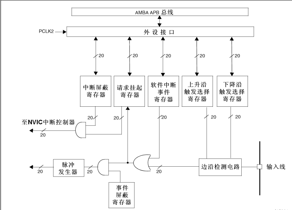
For interconnect products (series 105, 107), the external interrupt/event controller consists of 20 edge detectors that generate events/interrupt requests. For other models, there are 19 edge detectors that can generate events/interrupt requests.
Each input line can be independently configured for input type (pulse or suspended) and corresponding trigger events (rising edge, falling edge, or both edges). Each input line can also be individually masked. The pending register holds the interrupt requests of the status lines.
In short: EXTI is a detector that sends an interrupt request to NVIC when it detects a qualifying edge (here we only discuss interrupts).
Block diagram of the external interrupt/event controller:
Nested Vectored Interrupt Controller (NVIC)
NVIC stands for Nested Vectored Interrupt Controller, which is a peripheral of the M3 core that controls the interrupt-related functions of the chip. Since ARM has reserved many functions for NVIC, companies designing chips with the M3 core may not need so many functions, so NVIC needs to be trimmed. The number of internal interrupts of ST’s STM32F103 chip is the result of NVIC trimming. The interrupt control-related registers are within the NVIC structure in the firmware library core_cm3.h file. Any library function project can be opened to view it. NVIC is closely connected to the processor core, enabling low-latency interrupt handling and efficient processing of late-arriving interrupts.
The STM32F103 chip supports 60 maskable interrupt channels, and each interrupt channel has its own interrupt priority control byte. These interrupt priority control bytes consist of 8 bits, but in the STM32F103 chip, only the high 4 bits are used, i.e., 4 bits for priority.
In the STM32F103 chip, interrupt priorities are divided into preemptive priority and response priority (sub-priority or secondary priority). Preemptive priority is used to determine whether an interrupt event can interrupt the currently executing main program or interrupt program, while response priority is used to determine the relative priority of interrupts under the same preemptive priority.
When two interrupts have the same preemptive priority, the interrupt with the higher response priority will be responded to and processed first. In other words, if two interrupts arrive simultaneously, the interrupt with the higher response priority will be processed first.
When two interrupts have different preemptive priorities, the interrupt with the higher preemptive priority can interrupt the currently executing lower preemptive priority interrupt. In this case, interrupt nesting occurs, and the high preemptive priority interrupt will interrupt the currently executing lower preemptive priority interrupt and begin executing its own interrupt service routine.
When two interrupts have the same preemptive priority, if one interrupt is being processed and another arrives, the latter must wait until the previous interrupt is processed before it can be handled. If both interrupts arrive simultaneously, the interrupt controller will decide which interrupt to process first based on their response priorities. If both their preemptive and response priorities are equal, the order in the interrupt table will determine which one is processed first.
In short: The function of NVIC is to manage and control the priority of interrupts and the execution of interrupt service routines.
Of course, this is a metaphysical explanation; to put it simply, NVIC should be thought of as a “bathroom manager” that controls the urgency of interrupts and manages nested interrupts and “cleans the bathroom”.

It sounds complicated, but in practice, complex operations have been encapsulated, and we only need a few lines of code to complete the setup.
For example, the code to configure NVIC from the previous article:
/*Configure GPIO pin : PtPin */ GPIO_InitStruct.Pin = KEY_Pin; GPIO_InitStruct.Mode = GPIO_MODE_IT_RISING; GPIO_InitStruct.Pull = GPIO_NOPULL; HAL_GPIO_Init(KEY_GPIO_Port, &GPIO_InitStruct); /* EXTI interrupt init*/ HAL_NVIC_SetPriority(EXTI2_IRQn, 0, 0); HAL_NVIC_EnableIRQ(EXTI2_IRQn);By using HAL_NVIC_SetPriority(EXTI2_IRQn, 0, 0); and HAL_NVIC_EnableIRQ(EXTI2_IRQn); we set the priority and enable the interrupt.
For more details, you can refer to this article: Detailed Analysis of Interrupt Functions in STM32 HAL Library – NVIC
Interrupt function call flow: Interrupt service function EXTIx_IRQHandler() → Common interrupt handling function HAL_GPIO_EXTI_IRQHandler() → Interrupt callback function HAL_GPIO_EXTI_Callback().
In startup_stm32f105xc.s, the interrupt service functions corresponding to various interrupts are defined.
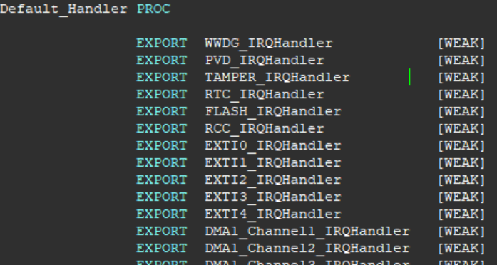
Taking EXTI2 corresponding to GPIOC_PIN2 as an example, you can find EXTI2_IRQHandler as its interrupt service function in the above image. The following [WEAK] indicates that it is a weak definition, and the user can redefine it.
EXTIx_IRQHandler()
Also, referring to the interrupt light-up example from the previous article, when the button is pressed and released, EXTI2 detects a rising edge and sends an interrupt request to NVIC:
Specifically, EXTI will send the following information to NVIC:
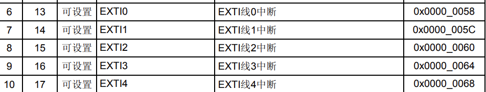
Interrupt source identification: EXTI will inform NVIC which external interrupt source (corresponding EXTI line) triggered the interrupt. This identifier can be used to distinguish different interrupt sources. In this instance, the specific Interrupt Numbers corresponding to EXTI2 are:
EXTI2_IRQn = 8, /*!< EXTI Line2 InterruptPending interrupt request: EXTI sends a pending interrupt request to NVIC to notify it that an interrupt event needs to be processed. This way, NVIC can respond accordingly to handle the interrupt.
After NVIC receives the interrupt request, it accesses the interrupt vector table based on the interrupt number provided by EXTI and jumps to the address of the corresponding interrupt service routine for execution.
The interrupt service function corresponding to EXTI2 is EXTI2_IRQHandler().
Partial EXTI interrupt vector table (interconnect type):
Definition of EXTI2_IRQHandler function:
void EXTI2_IRQHandler(void){ /* USER CODE BEGIN EXTI2_IRQn 0 */ /* USER CODE END EXTI2_IRQn 0 */ HAL_GPIO_EXTI_IRQHandler(KEY_Pin); /* USER CODE BEGIN EXTI2_IRQn 1 */ /* USER CODE END EXTI2_IRQn 1 */}HAL_GPIO_EXTI_IRQHandler()
The EXTI2_IRQHandler function calls HAL_GPIO_EXTI_IRQHandler, which is the common interrupt handling function for GPIO.
Below is the function definition in this instance:
void HAL_GPIO_EXTI_IRQHandler(uint16_t GPIO_Pin){ /* EXTI line interrupt detected */ if (__HAL_GPIO_EXTI_GET_IT(GPIO_Pin) != 0x00u) { __HAL_GPIO_EXTI_CLEAR_IT(GPIO_Pin); HAL_GPIO_EXTI_Callback(GPIO_Pin); }}Let’s analyze the functionality of this function step by step:
Check interrupt flag: The if statement checks whether the interrupt flag for the specified GPIO_Pin is set. The __HAL_GPIO_EXTI_GET_IT(GPIO_Pin) function is used to check the interrupt flag.
Clear interrupt flag: The __HAL_GPIO_EXTI_CLEAR_IT(GPIO_Pin) function is called to clear the interrupt flag. This is done to prevent repeated triggering of the interrupt.
Call callback function: The HAL_GPIO_EXTI_Callback(GPIO_Pin) function is called. This function is the callback function registered by the user during initialization. It is used to handle specific interrupt events related to GPIO_Pin.
HAL_GPIO_EXTI_Callback()
The system provides a __weak void HAL_GPIO_EXTI_Callback(uint16_t GPIO_Pin), which is a weak function defined as follows:
__weak void HAL_GPIO_EXTI_Callback(uint16_t GPIO_Pin){/* Prevent unused argument(s) compilation warning / UNUSED(GPIO_Pin); / NOTE: This function should not be modified, when the callback is needed, the HAL_GPIO_EXTI_Callback could be implemented in the user file }This function serves as a placeholder, providing a default callback function implementation in the library. Users can implement the HAL_GPIO_EXTI_Callback function in their own files according to their needs to handle the corresponding GPIO pin interrupt events. The UNUSED macro is used to mark the unused GPIO_Pin parameter to avoid compiler warnings about unused parameters.
In this instance, we directly define this function in main.c:
void HAL_GPIO_EXTI_Callback(uint16_t GPIO_Pin){ ms_Delay(50); if(GPIO_Pin == KEY_Pin) { if(HAL_GPIO_ReadPin(GPIOE, KEY_Pin) == 0) { HAL_GPIO_TogglePin(GPIOC, LED0_Pin); } }}Let’s analyze the functionality of this function step by step:
Delay function call: First, the ms_Delay(50) function is called, which is a delay function used to add a waiting time in the interrupt callback function. The specific delay time is 50 milliseconds.
Determine GPIO pin: Next, a conditional statement checks whether GPIO_Pin equals KEY_Pin. This is to ensure that the callback function only processes interrupt events related to KEY_Pin.
Read GPIO pin status: The HAL_GPIO_ReadPin function is used to read the status of the KEY_Pin pin on port GPIOE. If the pin status is low (0), the following operation is executed.
Control LED pin status: The HAL_GPIO_TogglePin function is used to toggle the state of the LED0_Pin pin on port GPIOC. This operation changes the LED’s state from on to off or from off to on.


Click Read the Original to purchase the OriginCar smart robot kit.