
Having worked in the embedded industry for seven or eight years, I would like to share some hardware circuit design schemes and insights for those who are new to embedded systems.
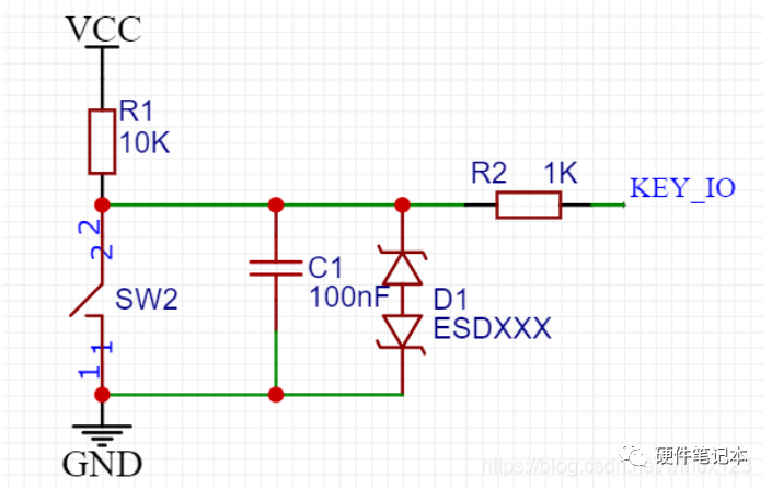
R1 Pull-up Resistor:
It clamps the uncertain signal to a high level through a resistor, maintaining it in a non-triggered state or returning to its original state after being triggered.(I personally recommend adding this)
C1 Capacitor:
Reduces button bounce and high-frequency signal interference.(I personally recommend adding this)
R2 Current-limiting Resistor:
Protects the IO port from overcurrent and high voltage damage, and absorbs static electricity or high-voltage pulses.(I personally recommend adding this)
The value of R2 can vary from 100 ohms to 10k. If internal pull-up is set, this value should not be too large; otherwise, the current will be insufficient to pull down the IO port.
D1 ESD Diode:
Static protection diode, prevents static interference or damage to the IO port.(This depends on the PCB cost and protection level requirements to decide whether to add it)
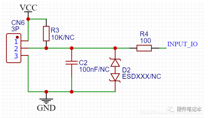
R3 Pull-up Resistor:
It clamps the uncertain signal to a high level through a resistor, maintaining it in a non-triggered state or returning to its original state after being triggered.(If the external connection wire is relatively long and the internal pull-up capability of the chip is weak, it is recommended to add this. If the communication distance is not long and there is internal pull-up, it can be omitted)
C2 Capacitor:
Prevents high-frequency signal interference.(Note, if the input frequency signal is relatively large, the value of C2 should be reduced accordingly, or C2 can be omitted)
R4 Current-limiting Resistor:
Protects the IO port from overcurrent and high voltage damage, and absorbs static electricity or high-voltage pulses.(I personally recommend adding this)
D2 ESD Diode:
Static protection diode, prevents static interference or damage to the IO port.(This depends on the PCB cost and protection level requirements to decide whether to add it)
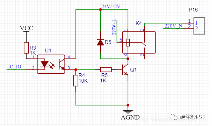
U1 Optocoupler:
Isolates high and low voltage, preventing high voltage interference and achieving electrical isolation.
D5 1N4148:
Flyback diode, protects components from being punctured or burned by induced voltage, connected in parallel to the components generating induced electromotive force to form a loop, consuming the generated high electromotive force in the loop as flyback current, thus protecting the components in the circuit from damage.
Darlington transistors are commonly used by friends for stepper motor driving; they can also be used for motor speed control, high-power switching circuits, driving relays, and driving high-power LED light sources, using PWM to adjust brightness.
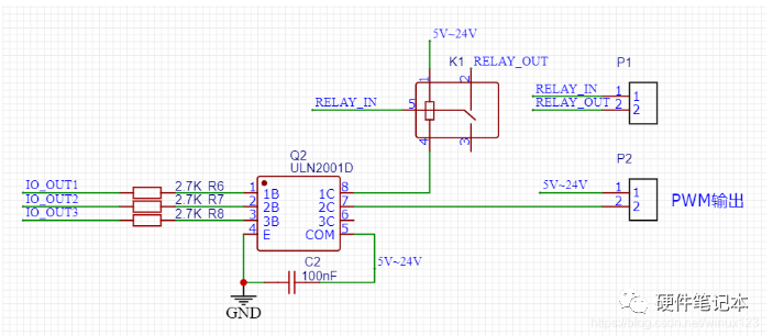
R6, R7, R8 Resistors:
Used for current limiting to prevent ULN2001 from being damaged, resulting in high voltage directly input to the MCU’s IO.(Since ULN2001D itself has a built-in 2.7K resistor, R6, R7, R8 can be omitted here; if certain driver chips do not have resistors, it is best to add them yourself; specific situations can be checked in the selected chip’s data sheet to decide)
COM Terminal Connected to Power Supply:
When the output terminal is connected to an inductive load, the load does not need to add a flyback diode, as the chip has a diode designed internally; just connect the COM port to the load power supply. When connecting to other loads, the COM port can be left unconnected.
When using a resistor-capacitor voltage reduction circuit to supply power to ULN2001D, since the resistor-capacitor voltage reduction cannot prevent transient high voltage fluctuations on the power line, it is necessary to connect a 104 capacitor close to the COM terminal of ULN2001D and the ground terminal. In other application scenarios, this capacitor can be omitted.
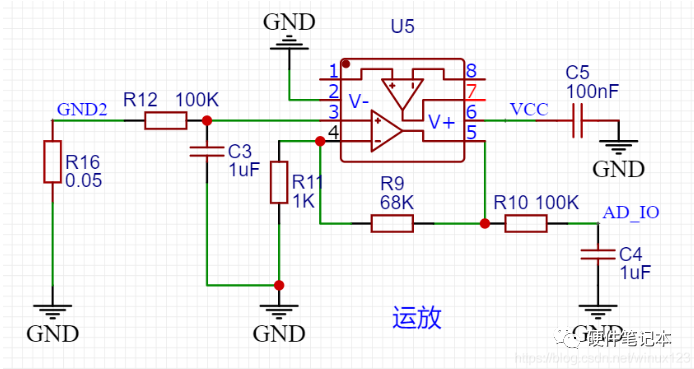
Using an operational amplifier to cleverly sample the current of the load can accurately determine the current operating condition of the load and whether it is functioning normally, which is very useful.
GND2 is the ground terminal of the load, connected to the common ground through R16 resistor(Choose a higher power rating for R16 based on the load current), there will be a slight voltage difference.
This circuit is a non-inverting proportional operational circuit, so the voltage at the sampling terminal = input voltage * (1 + R9/R11) = 69 times the input voltage. You can modify R9 to adjust the amplification factor according to the measurement range.
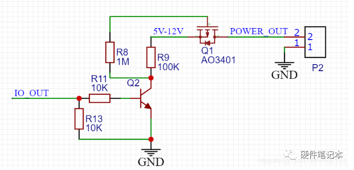
6. MOSFET
Controls the power output on and off
7. Input Power Supply
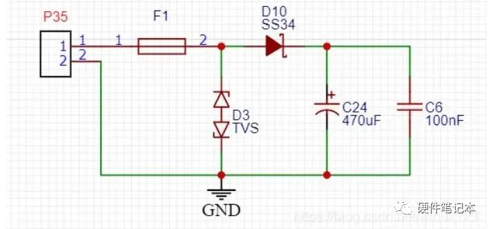
If the circuit cost is tight, you can appropriately reduce components as needed.
F1 Self-recovery Fuse:
Overcurrent protection, can adjust the threshold size based on actual load current.
D10 Schottky Diode:
Reduces the impact of the downstream power supply on the upstream, prevents damage to the downstream circuit from reverse polarity of the power supply, and prevents current backflow when the power supply is turned off. However, there is about 0.4V voltage drop across the diode, so it is necessary to consider whether the voltage after the 0.4V drop will be lower than the normal operating voltage of the downstream circuit.
TVS Diode:
Overvoltage protection for input voltage, generally taken as 1.4 times the normal input voltage.
* Copyright statement: This article is an original piece by CSDN blogger “Fish and Feather”, following the CC 4.0 BY-SA copyright agreement. Please include the original source link and this statement when reprinting.
* Original link: https://blog.csdn.net/winux123/article/details/107307470


With just over a month left until the New Year, the breadboard community is launching the year-end couplet activity as usual.
As per tradition, write couplets that are original and related to the electronics industry.
Activity Rewards:
4 pairs of “Best Couplets”, each person receives a 100 yuan JD E-card.
5 pairs of “Excellent Participation”, each person receives a 30 yuan JD E-card.
How to Participate:
Click the “Read the original text” button in the lower left corner to reply to the post!