Basic Working Principle of ADC
Source: CSDN Blogger:xtmtm
ADC ( analog to digital converter ) conversion process
The basic conversion principle of ADC is divided into four processes:
① Anti-aliasing filter ( Anti-aliasing ), which can be understood as a low-pass filter
② Sample and hold circuit ( Sample and hold )
③ Quantization ( Quantizer )
④ Encoding ( Coder )
Sample and hold
The so-called sampling is to convert a continuously varying analog quantity in time into a discretely varying analog quantity in time. The result of the sampling is stored until the next sampling; this process is called holding.
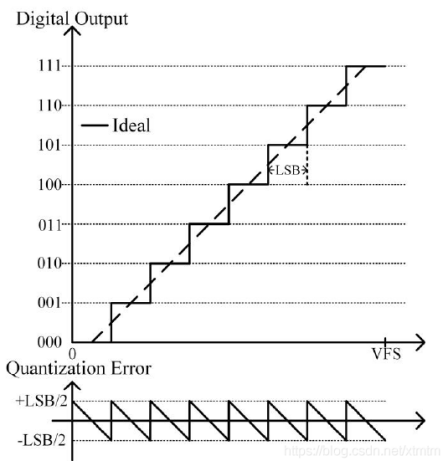
Quantization and encoding
The process of converting an analog signal into a digital signal through ADC is called quantization. Due to the limited bit depth of the quantized output digital signal, there will be an error between the output digital signal and the sampled analog signal, referred to as quantization error. For an N-bit ADC, assuming its full-scale voltage is Vref, Vref is divided into 2N intervals by the ADC, and the interval width is represented by LSB ( last significant bit ) which is LSB=Vref/2N.
For example: Vref=8V, ADC is 3 bits, LSB=1, so each interval is 1V,
000 represents voltage 0≤V<1
001 represents voltage 1≤V<2
010 represents voltage 2≤V<3
011 represents voltage 3≤V<4
100 represents voltage 4≤V<5
101 represents voltage 5≤V<6
110 represents voltage 6≤V<7
111 represents voltage 7≤V<8
The resolution of this ADC is 1V
Classification of ADC
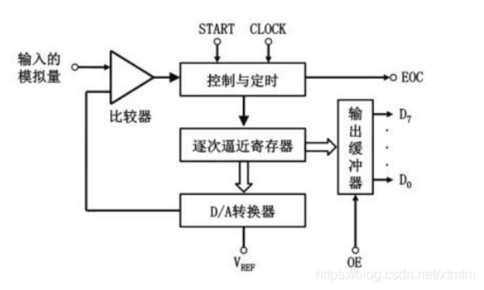
① Successive approximation ADC
The basic principle is to compare each bit from high to low, similar to weighing an object with a balance, incrementally adding or removing weights from heavy to light for trial. The successive approximation conversion process is: at initialization, all bits of the successive approximation register are cleared; when the conversion starts, the highest bit of the successive approximation register is set to 1, sent to the D/A converter, and the analog quantity generated after D/A conversion is sent to the comparator, called Vo, and compared with the analog quantity to be converted Vi. If Vo<Vi, that bit 1 is retained; otherwise, it is cleared. Then the next highest bit of the successive approximation register is set to 1, and the new digital quantity in the register is sent to the D/A converter, and the output Vo is compared with Vi. If Vo<Vi, that bit 1 is retained; otherwise, it is cleared. This process is repeated until the lowest bit of the register is approached. After the conversion is complete, the digital quantity in the successive approximation register is sent to the buffer register to obtain the digital output.
② Dual-slope ADC
The basic principle is to convert the input voltage into a time interval that is proportional to its average value, and then convert the time interval into a digital quantity, which is an indirect conversion. The conversion process is: first, the switch is turned on to connect the analog quantity to be converted Vi, Vi is sampled into the integrator, which integrates positively for a fixed time T starting from zero. After time T, the switch is turned on to connect the reference voltage Vref with the opposite polarity to Vi, inputting Vref to the integrator for negative integration until the output is 0V to stop integration. The larger Vi is, the larger the output voltage of the integrator, and the longer the negative integration time. The value counted by the counter during the negative integration time is the digital quantity corresponding to the analog voltage Vi, realizing A/D conversion.

③ Full parallel / parallel-serial ADC
Parameters of ADC
① Resolution
The change in the analog signal when the digital quantity changes by a minimum amount, defined as the ratio of full scale to 2n, usually expressed in the number of bits of the digital signal.
② Conversion rate
The conversion rate refers to the reciprocal of the time required for one A/D conversion, that is, the number of A/D conversions completed in unit time.
③ Sampling rate
The sampling rate is the reciprocal of the interval time between two samplings (two conversions). To ensure the correct completion of the conversion, the sampling rate must generally be less than or equal to the conversion rate, that is, the sampling time must be greater than or equal to the conversion time.
[1] Hu Renren. A design of an 8-channel 12-bit 1MS/s SAR ADC [D]. Electronic Science and Technology University, 2020.
[2] Zhang Qingjie, Xu You. Teaching you to learn DSP step by step — based on TMS320F28335 (second edition) [M]. Beijing: Beihang University Press, 2018.